Quick Changer Quick Changer
for I/O
Dual Quick
Changer
Quick Changer -
Tool Side
Units
Weight
0.06
0.13
0.093
0.21
0.41
0.9
0.14
0.31
[kg]
[lb]
Dimensions See Mechanical dimension section
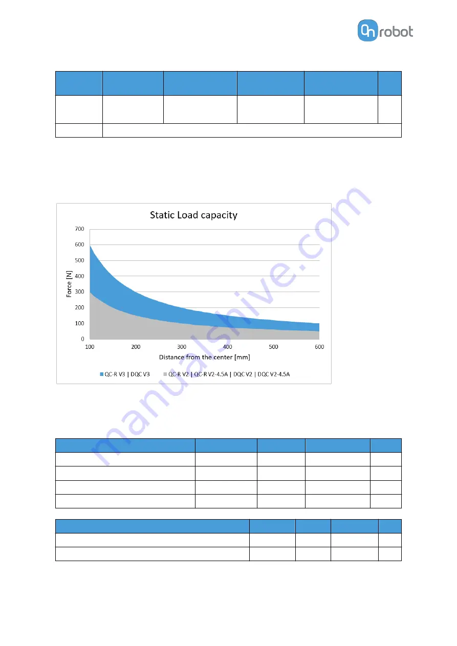
QC-R V3 | DQC V3 and the QC-R V2 | QC-R V2-4.5A | DQC V2 | DQC V2-4.5A
The following graph shows the load capacity that the QC-R V3 | DQC V3 and the QC-R V2 |
QC-R V2-4.5A | DQC V2 | DQC V2-4.5A can handle in a static situation. The values for a
situation with an acceleration of 2g are half of the static values.
8.1.3. Compute Box
8.1.3.1. With 6.25A Wall Adapter (150W)
Supplied Wall Adapter
Minimum
Typical
Maximum
Unit
Input voltage (AC)
100
-
240
[V]
Input current
-
-
2.1
[A]
Output voltage
-
24
-
[V]
Output current
-
6.25
-
[A]
Compute Box Power input (24V connector)
Minimum
Typical Maximum
Unit
Supply voltage
-
24
25
[V]
Supply current
-
6.25
-
[A]
HARDWARE SPECIFICATION
68
Summary of Contents for 2FGP20
Page 1: ...USER MANUAL FOR UR ROBOTS v1 13 0 Original Instructions...
Page 62: ...Illustration Pad position Maximum force N 2 200 3 100 4 400 HARDWARE SPECIFICATION 62...
Page 71: ...8 2 3 Tools 8 2 3 1 2FGP20 All dimensions are in mm and inches HARDWARE SPECIFICATION 71...
Page 79: ...12 Certifications CERTIFICATIONS 79...
Page 80: ...12 1 EMC 12 2 2FGP20 Environment CERTIFICATIONS 80...
Page 81: ...12 3 Declaration of Incorporation 12 3 1 2FGP20 CERTIFICATIONS 81...


