Installation
19
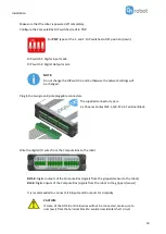
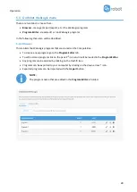
Make sure that the robot is powered off completely.
Configure the Compute Box DIP switches (red) to PNP:
For
PNP
type set the 1. and 2. DIP switches to OFF position (down).
DIP switch 1: Digital Input mode
DIP switch 2: Digital Output mode
NOTE:
Do not change the DIP switch 3 and 4 otherwise the network settings will
be changed.
Plug in the two green 8 pole pluggable connectors.
The supplied connector type is:
2 x Phoenix Contact MC 1,5/8-ST-3,5 Terminal Block.
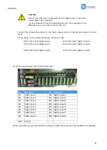
Wire the digital I/O wires from the Compute Box to the robot.
DO1-8
: Digital outputs of the Compute Box (signals from the grippers/sensor to the robot)
DI1-8
: Digital inputs of the Compute Box (signals from the robot to the grippers/sensor)
It is recommended to connect all 8 inputs and 8 outputs for simplicity.
CAUTION:
If some of the DO1-8 or DI1-8 wires will not be connected, make sure to
unscrew it from the terminal block to avoid an accidental short circuit.
Summary of Contents for DOOSAN Gecko Gripper
Page 1: ...USER MANUAL FOR DOOSAN ROBOTS ORIGINAL INSTRUCTION EN v1 02...
Page 79: ...Hardware Specification 79 RG2 Gripping Speed Graph RG2 Work Range...
Page 82: ...Hardware Specification 82 RG6 Gripping Speed Graph RG6 Work Range...
Page 93: ...Hardware Specification 93 RG2 FT All dimensions are in mm and inches...
Page 94: ...Hardware Specification 94 RG2 All dimensions are in mm and inches...
Page 95: ...Hardware Specification 95 RG6 All dimensions are in mm and inches...
Page 96: ...Hardware Specification 96 VG10 All dimensions are in mm and inches...
Page 97: ...Hardware Specification 97 All dimensions are in mm and inches...
Page 98: ...Hardware Specification 98 Quick Changer Tool side All dimensions are in mm and inches...
Page 104: ...Certifications 104 10 Certifications...
Page 105: ...Certifications 105...


