Installation
20
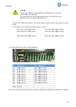
CAUTION:
The 24V and GND pins are only Reference Voltage Output. It cannot be
used to power any equipment.
It is recommended to use the supplied wires only. If it is necessary to use
different wire, use one that is shorter than 3 m.
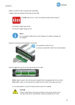
Connect the Compute Box inputs to the robot outputs and the Compute Box outputs to robot
inputs.
For simplicity, it is recommended to map the pins in order:
DO1 to the robot's Digital input 1
DO2 to the robot's Digital input 2
…
DO8 to the robot's Digital input 8
DI1 to the robot's Digital output 1
DI2 to the robot's Digital output 2
…
DI8 to the robot's Digital output 8
List of the important pins of the IO terminal blocks:
Pin
Description
Pin
Description
I01
Digital input 1
O01 Digital output 1
I02
Digital input 2
O02 Digital output 2
I03
Digital input 3
O03 Digital output 3
I04
Digital input 4
O04 Digital output 4
I05
Digital input 5
O05 Digital output 5
I06
Digital input 6
O06 Digital output 6
I07
Digital input 7
O07 Digital output 7
I08
Digital input 8
O08 Digital output 8
GND
Ground
Please note which pin you used during the wiring, in a later step it is going to be needed for the mapping.
Summary of Contents for DOOSAN Gecko Gripper
Page 1: ...USER MANUAL FOR DOOSAN ROBOTS ORIGINAL INSTRUCTION EN v1 02...
Page 79: ...Hardware Specification 79 RG2 Gripping Speed Graph RG2 Work Range...
Page 82: ...Hardware Specification 82 RG6 Gripping Speed Graph RG6 Work Range...
Page 93: ...Hardware Specification 93 RG2 FT All dimensions are in mm and inches...
Page 94: ...Hardware Specification 94 RG2 All dimensions are in mm and inches...
Page 95: ...Hardware Specification 95 RG6 All dimensions are in mm and inches...
Page 96: ...Hardware Specification 96 VG10 All dimensions are in mm and inches...
Page 97: ...Hardware Specification 97 All dimensions are in mm and inches...
Page 98: ...Hardware Specification 98 Quick Changer Tool side All dimensions are in mm and inches...
Page 104: ...Certifications 104 10 Certifications...
Page 105: ...Certifications 105...


