NOTE:
For the Quick Changer - Robot Side no cable is needed to be connected.
4.4.1. Tool Data Cable
4.4.1.1. RG2-FT
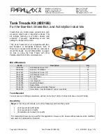
First connect the data cable to the tool.
For RG2-FT the Quick Changer tool data
connector cannot be used. Instead use the
marked M8-4pin connector.
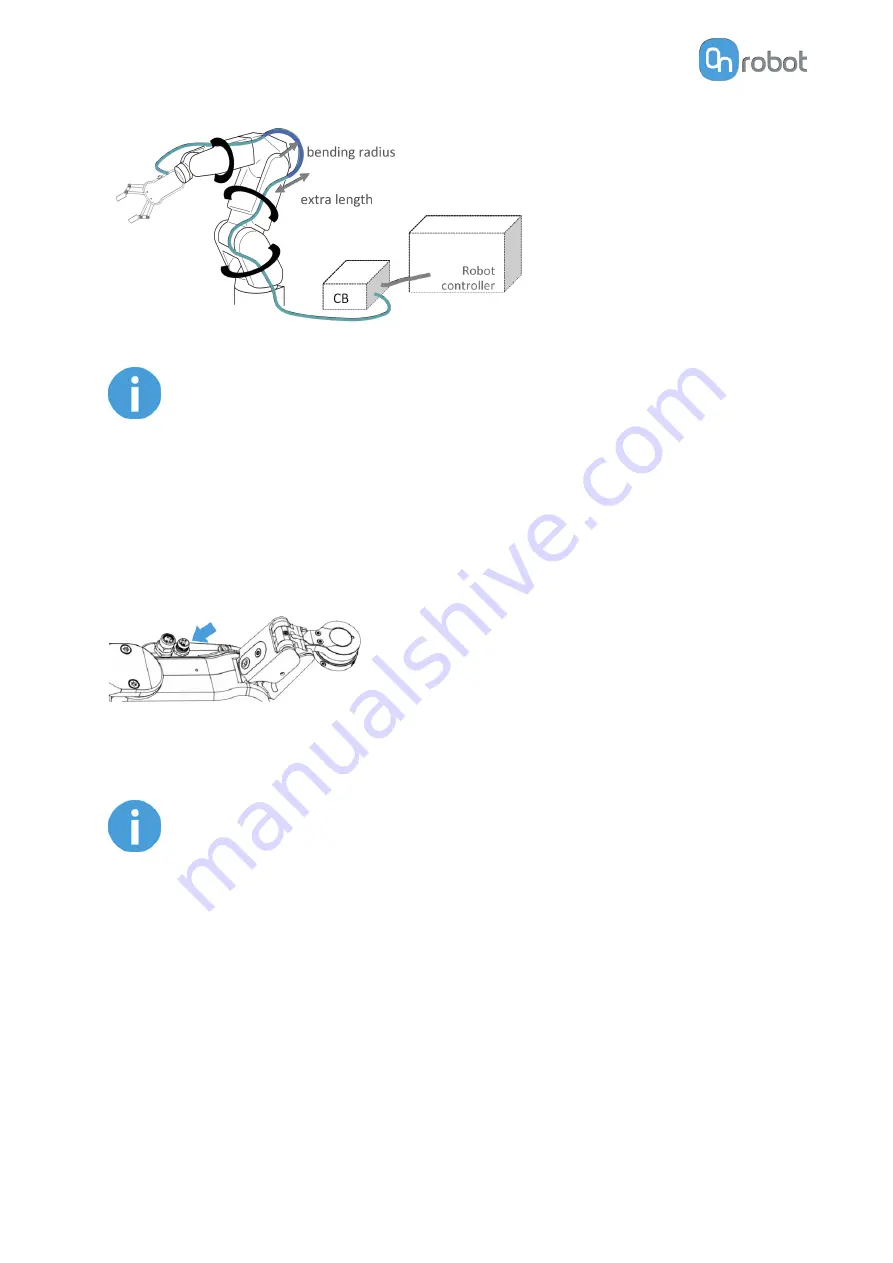
Then route the Tool data cable to the Compute Box (CB) and use the supplied Velcro tape
(black) to fix it.
NOTE:
Make sure that during the routing some extra length is used at the joints so
that cable is not pulled when the robot moves.
Also make sure that the cable bending radius is minimum 40mm (for the HEX-
E/H QC it is 70mm).
Finally, connect the other end of the Tool data cable to the Compute Box's DEVICES
connector.
HW INSTALLATION
14
Summary of Contents for RG2-FT
Page 1: ...USER MANUAL FOR UR ROBOTS v1 4 1 Original Instructions ...
Page 66: ...Proximity Sensor Typical Accuracy HARDWARE SPECIFICATION 66 ...
Page 68: ...Dimensions of the Gripper s finger in millimeters HARDWARE SPECIFICATION 68 ...
Page 74: ...8 2 4 Tools 8 2 4 1 RG2 FT All dimensions are in mm and inches HARDWARE SPECIFICATION 74 ...
Page 82: ...12 Certifications CERTIFICATIONS 82 ...
Page 83: ...12 1 EMC CERTIFICATIONS 83 ...
Page 84: ...12 2 Declaration of Incorporation 12 2 1 RG2 FT CERTIFICATIONS 84 ...


