background image

Section 3: Modules and Sensors 

HOBO Energy Logger User’s Guide 

17 

Section 3:


 Modules and Sensors 

This section provides details on working with modules and sensors. 

Adding and Removing Modules and Sensors 

Whenever possible, it is best to add and remove modules and sensors 
between deployments – after stopping the logger and reading out data, 
but before relaunching. However, circumstances may require that you 
add or remove a module or sensor at some other time. 

If you 

add 

a module or sensor while the logger is recording data, the 

module or sensor will be ignored. Logging will continue normally for the 
other channels.  

You may attach modules and sensors at the following times:  


Any time between deployments, when the logger is stopped. 


While you are configuring the launch parameters in HOBOware. 
Click 

Refresh 

to update the 

Logging Duration 

and see the new 

module or sensor added to the list of sensors. 


After you have launched the logger, but before logging has 
begun (i.e. when the logger is waiting for a delayed or button 
start). Note that adding modules or sensors will cause the 
logging duration to be shorter than the duration that was 
displayed in the Launch window. 

If you 

remove 

a module or sensor while the logger is logging, the 

Sensor Fail 

indicator will blink when the next logging interval is 

reached, and the logger will record erroneous data for that channel. This 
is true even if you immediately connect another sensor of the same type 
in the same port. If you want to change sensors – even sensors of the 
same type – you must stop the logger, read it out, swap the sensors, and 
then relaunch. 

Smart Sensor Cables 

The logger can work with a maximum total of Smart Sensor cable 
lengths up to 100 meters (328 feet), as measured from the logger 
connection point to the electronics embedded in the individual cables. 
Optional Smart Sensor extension cable lengths must also be included in 
the total. 

Section 3: Modules and Sensors 

18 


HOBO Energy Logger User’s Guide 

This limitation applies to Smart Sensor cables only. The lengths of other 
cables, such as those connected to FlexSmart modules, do not need to be 
included in this total. 

Analog (CVIA) Module 

The Analog module (S-FS-CVIA) is an easy-to-configure, flexible DC 
signal-conditioning module for the HOBO Energy Logger. This two-
channel module can accept (and provide excitation power to) a wide 
range of Onset and third-party sensors with 0-0 V or 0-20 mA output, 
including devices with 4-20 mA current loop interface, and sensors with 
0-2.5, 0-5, and 0-10 V DC output.  

The Analog module features input protection and signal filtering, as well 
as delta-sigma A/D conversion and factory calibration. This module 
features extremely low-power operation, resulting in long battery life for 
unattended data logging applications. Precision electronics provide 
±0.25% accuracy from 50 mV to full scale (FS). 

Sensors connected to this Analog module can be configured in 
HOBOware software. Configuration options include channel names, 
scaling parameters, and excitation power. Sensors are connected to the 
module via a seven-pin Phoenix-style detachable screw terminal 
connector. 

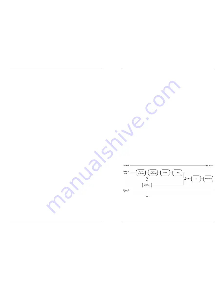
Functional Block Diagram 


Figure 3: Analog Module - Functional Block Diagram 

w

w

w

.

G

lo

ba

lTe

st

Su

pp

ly

.c

om

Fin

d Q

ua

lit

y P

ro

du

ct

s O

nli

ne

 a

t:

sa

le

s@

G

lo

ba

lTe

st

Su

pp

ly.c

om

Summary of Contents for H22-001

Page 1: ...and lock out all power sources during installation and servicing Please read the user s manual for instructions and use 2009 2017 Onset Computer Corporation All rights reserved Onset HOBO HOBOware and...

Page 2: ...e 19 Configuring Channels on the Analog Module 20 Verifying Operation 20 Sensor Excitation 20 Working with Channels 22 Section 4 Batteries and External Power 23 Selecting batteries 23 iv HOBO Energy L...

Page 3: ...rgy Logger Energy Logger User s Guide Eight 1 5V alkaline batteries One miniature slotted screwdriver Blank label Rubber feet Section 1 Introduction 2 HOBO Energy Logger User s Guide Specifications Op...

Page 4: ...gging begins Automatic detection of Smart Sensors The logger automatically recognizes Smart Sensors No programming wiring or calibration is required to set them up Digital network The connections betw...

Page 5: ...was selected in HOBOware during launch Indicator LEDs There are three green and three red status indicators The green indicators blink to show status or activity The red indicators blink to show that...

Page 6: ...rews Energy Logger Mounting Kit A H22 DINMOUNT 1 Allows you to mount the logger to industry standard 32 mm and 35 mm DIN rails Energy Logger Spares Kit A H22 SPARES Spare bumpers screwdriver and FlexS...

Page 7: ...tch the polarity marked in the battery compartment Refer to Selecting Batteries on page 23 for tips on selecting the right battery type for your application Replace the battery compartment door and ti...

Page 8: ...daptability HOBOware lets you configure these modules at launch time or create and save different configurations to be loaded into the modules whenever needed If you connected only Smart Sensors skip...

Page 9: ...O Energy Logger User s Guide Depending on the option you select the logger may start automatically either immediately or at a specified time or you may start it manually by pressing the Push to Start...

Page 10: ...elect a minimum 2 second logging interval If all TRMS modules are configured for single channel use you can use a 1 second logging interval 4 If you are using sensor excitation configure it for each F...

Page 11: ...stop the logger read it out swap the sensors and then relaunch Smart Sensor Cables The logger can work with a maximum total of Smart Sensor cable lengths up to 100 meters 328 feet as measured from th...

Page 12: ...cept a wide range of sensors That means that each channel can be configured to measure either current or voltage and the collected data can be scaled to produce meaningful results that are consistent...

Page 13: ...ogger s internal battery channel at launch If the battery becomes too low to provide excitation power excitation power is turned off but logging continues as long as the battery can power the logger T...

Page 14: ...For low current applications however they offer little improvement Section 4 Batteries and External Power 24 HOBO Energy Logger User s Guide Battery type Considerations for use Lithium Li FeS2 Lithium...

Page 15: ...Voltage Input Adapter S VIA CM14 Photosynthetically Active Radiation PAR S LIA M003 Silicon Pyranometer Solar Radiation S LIB M003 Note Although some Smart Sensors are intended mainly for outdoor use...

Page 16: ...Energy Logger User s Guide logger contact the vendor that sold it to you It may be possible to retrieve the logged data External Power Sources An external power source can reduce or eliminate the need...

Page 17: ...is scheduled for an extended deployment Verify logger operation Before each deployment Section 5 Maintenance 30 HOBO Energy Logger User s Guide Inspecting the Logger Housing and Cables Periodically p...

Page 18: ...ogger may lose up to two seconds when it is launched This is a one time error that occurs as part of the start up sequence and cannot be avoided Clock drift The logger s long term time accuracy is rel...

Page 19: ...ostics and Troubleshooting 34 HOBO Energy Logger User s Guide Section 7 Diagnostics and Troubleshooting This section lists some symptoms and tips to help you confirm correct operation of your logger a...

Page 20: ...significant capacity if stored at elevated temperatures Check the voltage of the batteries with a voltmeter Alkaline batteries should be at least 1 5 V per cell when new fresh lithium batteries shoul...

Page 21: ...both the logging and sampling intervals are set for at least one minute or greater Fast sampling and logging intervals shorter than one minute will rapidly deplete the battery For more information re...

Page 22: ...0 34 36 36 Logging interval 2 15 17 20 21 24 33 37 Measurement averaging See Sampling interval Memory 2 14 27 33 36 wrapping 13 14 35 Power adapter power supply see External power source Sampling inte...

Reviews: