HOBO
MicroRX
Station
for
HOBOnet
(RX2105
and
RX2106)
Manual
1
‐
800
‐
LOGGERS
5
www.onsetcomp.com
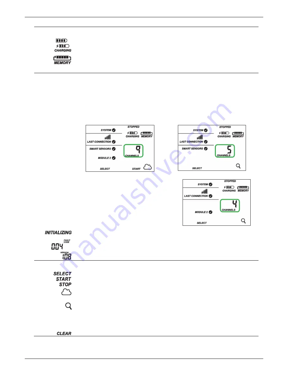
Battery
and
Memory
Status
This
part
of
the
LCD
shows
the
current
battery
level
and
memory.
or
The
battery
indicator
shows
the
approximate
battery
power
remaining.
In
this
example,
the
battery
is
fully
charged.
The
lightning
bolt
will
appear
when
an
AC
adapter
or
solar
panel
is
plugged
into
the
station.
“Charging”
will
flash
while
the
battery
is
being
charged.
When
the
station
is
logging,
it
will
record
data
indefinitely,
with
newest
data
overwriting
the
oldest
data
until
the
station
is
stopped.
This
continuous
logging
is
represented
by
the
arrow
in
this
symbol.
With
normal
communication,
the
memory
used
will
be
small,
and
this
icon
will
show
one
bar.
If
the
station
is
not
able
to
connect
to
HOBOlink,
this
icon
will
show
the
amount
of
memory
that
is
filled
with
data
waiting
to
be
read
out
at
the
next
connection.
Channel
and
Device
Information
This
part
of
the
LCD
shows
the
number
of
channels
and
other
information
about
each
module.
It
also
shows
general
device
information.
Press
the
Select
button
to
scroll
through
the
main
screen,
smart
sensors
screen,
and
module
2
for
the
manager.
Main
Screen
When
viewing
the
main
LCD
screen,
the
total
number
of
all
channels
in
use
by
the
system
is
displayed.
This
is
a
combination
of
smart
sensor
channels
and
wireless
network
channels.
For
example,
if
there
are
5
smart
sensor
channels
and
4
wireless
network
channels,
then
9
channels
are
shown
on
the
main
screen
as
shown.
Smart
Sensors
Screen
When
viewing
the
smart
sensors
screen,
the
number
of
smart
sensor
channels
is
displayed.
Note
that
some
smart
sensors
have
more
than
one
channel
associated
with
them
so
the
number
of
channels
may
not
match
the
number
of
physical
smart
sensors.
In
this
example,
there
are
5
smart
sensor
channels.
Module
2
When
viewing
the
module
2
screen,
information
about
the
manager
is
displayed.
The
channel
count
represents
all
measurement
channels
plus
a
battery
channel
for
each
mote
in
the
wireless
network.
For
example,
one
temperature/RH
wireless
sensor
and
one
repeater
has
a
channel
count
of
four
as
shown
at
right.
This
will
blink
in
the
lower
right
part
of
the
LCD
when
a
firmware
update
is
underway.
It
will
display
which
module
or
element
is
being
updated.
This
is
a
numerical
code
that
appears
when
a
system
fault
has
occurred.
You
may
need
to
provide
this
code
to
Onset
Technical
Support.
See
Troubleshooting
for
details.
This
is
the
version
number
of
the
station
firmware.
It
only
appears
when
powering
up
the
device.
Button
Symbols
Use
the
three
buttons
below
the
following
symbols
to
operate
the
station.
Press
any
of
the
three
buttons
to
turn
on
the
LCD.
Press
this
button
to
cycle
through
status
information
about
the
smart
sensors
and
module
2.
Press
this
button
to
start
logging.
This
option
is
not
available
while
the
station
is
actively
connected
to
HOBOlink.
Press
this
button
to
stop
logging.
This
option
is
not
available
while
the
station
is
actively
connected
to
HOBOlink.
Press
this
button
to
connect
to
HOBOlink.
This
option
is
only
available
on
the
main
LCD
screen.
It
is
not
available
when
scrolling
through
smart
sensor
and
module
information
with
the
Select
button.
In
addition,
this
option
is
not
available
while
a
connection
is
underway
or
active.
Press
this
Search
button
for
the
station
to
detect
all
currently
installed
smart
sensors
or
add
motes
to
your
wireless
network.
As
you
add
or
remove
smart
sensors
while
the
station
is
stopped,
press
the
Select
button
and
then
the
Search
button
for
the
system
to
recognize
your
changes.
This
option
is
not
available
for
smart
sensors
while
the
station
is
logging.
To
add
motes
to
the
wireless
network,
press
the
Select
button
to
switch
to
module
2
and
then
press
the
Search
button
for
the
station
to
find
the
motes.
The
station
can
search
for
motes
whether
it
is
logging
or
stopped.
Use
this
button
to
clear
a
fault
code.


