RG3 and RG3-M Data Logging Rain Gauge User’s Manual
5
Logger-to-Rain Gauge Connection
The logger’s black and white input wires are connected to the tipping-bucket
output by a terminal block as shown in Figure 1.
Logger Deployment Considerations
Ensure logger cable does not interfere with the operation of the tipping
bucket mechanism!
When logger is not deployed outside of the rain gauge
housing, cable should be neatly coiled with no sharp bends, secured with cable
ties, and placed between tipping bucket holder and logger holder (see Figure 1).
Logger should be placed securely in its holder.
Using the Logger for Temperature Measurement
To use the logger to record temperature, it must be deployed outside of the rain
gauge housing in a suitable solar radiation shield (such as those supplied by
Onset) to ensure accurate temperature measurements.
1.
If not already done, lift off the ring, screen, and funnel assembly and
then
carefully
cut any cable ties that secure the cable.
2.
Unscrew the two terminal block screws that secure the logger’s black
and white input wires.
Note:
Screws do not have to be completely
removed—only enough to slide out the wires.
3.
Remove logger and cable from housing.
4.
From outside of housing, feed the wire end of the cable through the
rubber grommet. Slide the wires back into the terminal block until no
bare wire is showing, but only far enough so that the terminal block
screws clamp down on the bare wire and not the black and white
insulation. (The polarity of the input connection is not important.)
Tighten the terminal block screws and then gently tug the wires to
ensure they are secure.
Make sure any excess cable inside of housing
is secured so that it does not interfere with the operation of the
tipping bucket mechanism!
If possible, create service loop for cable
by using two small cable ties to loop and secure cable to cable tie
mount (see Figure 2).
Figure 2: Service Loop
Cable Ties
6
RG3 and RG3-M Data Logging Rain Gauge User’s Manual
Connecting the Logger to Computer
The HOBO Event/Temperature data logger requires an Onset
-
supplied Optic
USB Base Station and Coupler (part no: BASE-U-1), and HOBOware version
2.1 or later software to connect to computer. If possible, avoid connecting at
temperatures below 0°C (32°F) or above 50°C (122°F).
1. Plug the USB connector on the base station into an available USB port on
your computer.
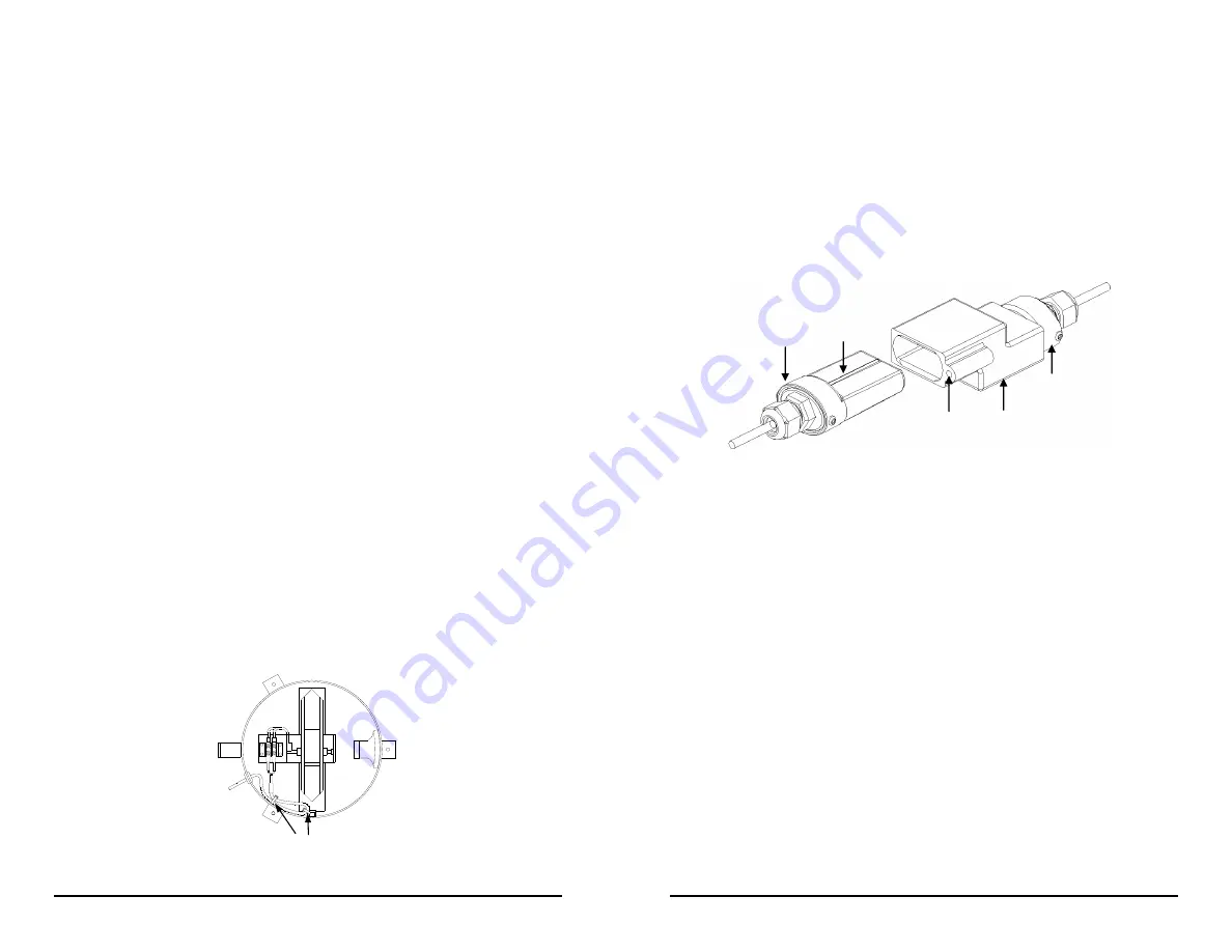
2. Insert the logger and the base station into the coupler, as shown in Figure 3.
Make sure that the logger is inserted in the end of the coupler that has the
magnet, and that the ridges on the base station and logger are aligned with
the grooves in the coupler.
Logger
Magnet
Base station
Coupler
Ridge
Figure 3: Inserting Logger into Base Station
3. If the logger has never been connected to the computer before, it may take a
few seconds for the new hardware to be detected.
4. Use the logger software to launch and read out the logger.
Note:
You can read out the logger or check its status while it continues to log,
stop it manually with the software, or let it record data until the memory is full.
Refer to the software user’s guide for complete details on launching, reading
out, and viewing data from the logger.
Logger Triggered Start
The logger can be configured to start logging at your command using the
magnet in the coupler or any strong magnet to trigger the start.
1. Use the logger software to launch the logger with
Trigger Start
selected for
the Default Launch Type. Remove the logger from the coupler.
2. Bring the logger and the empty coupler, or strong magnet, to the deployment
location.
Important: Any magnet can trigger a start. This can be helpful, but it
can also cause a premature start. Keep the logger away from strong
magnetic fields until you are ready to begin logging.


