RG3 and RG3-M Data Logging Rain Gauge User’s Manual
7
3. When you are ready for the logger to start logging, insert the logger into the
empty coupler (or place it next to a strong magnet) and remove it after three
seconds.
Important: The logger will not launch if the coupler is attached
to a base station.
4. Verify that the logger’s light is blinking at least every four seconds.
Internal Events
Like other U
-
Series loggers, this logger stores internal events that are unrelated
to the external event input. Internal events are stored when the coupler is
attached or detached, when the battery drops below approximately 2.7V, when
the battery rises above 2.8V, when a host computer is connected, and when the
logger is stopped by a command from the host software.
Logger Operation
A light (LED) on the front of the logger confirms logger operation. The
following table explains when the light blinks during logger operation.
When: The
light:
The logger is logging
Blinks once every one to four seconds (the
shorter the logging interval, the faster the light
blinks); blinks when logging a sample
The logger is awaiting a start
because it was launched in Start
At Interval, Delayed Start, or
Trigger Start mode
Blinks once every eight seconds until logging
begins
Data Storage
The data logger has 64,000 bytes of nonvolatile data storage. The logger records
a time stamp for each tipping-bucket tip. Data storage requirements per tip are a
function of enabled channels and logging interval. When tips are three to 12
days apart, 32 bits are required to record a single tip (16,000 tips). When tips are
less than 16 seconds apart, only 22 bits are required to record a single tip
(23,000 tips). In most cases, 25,000 to 30,000 data points (including tips,
temperature, and/or battery measurements) can be logged. For most rain gauge
applications, battery life, not memory capacity, will be the factor that limits
deployment duration.
Protecting the Logger
Do not store the logger in the coupler. Remove the logger from the coupler
when you are not using it. When the logger is in the coupler or near a magnet, it
consumes more power and will drain the battery prematurely.
Keep the logger away from magnets. Being near a magnet can cause false
coupler events to be logged. It can also launch the logger prematurely if it was
waiting for a trigger start.
8
RG3 and RG3-M Data Logging Rain Gauge User’s Manual
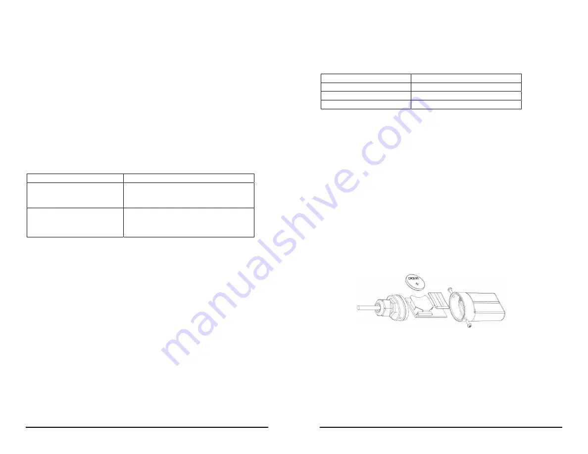
Figure 4: Battery Replacement
If the logger is used in a humid location, periodically inspect the desiccant and
dry it if it is not bright blue. To dry the desiccant, remove the desiccant pack and
leave the pack in a warm, dry location until the bright blue color is restored.
(Refer to the “Battery” section for instructions on removing and replacing the
logger cap.)
Temperature range
Desiccant maintenance schedule
Less than 30°C (86°F)
Approximately once per year
30° to 40°C (86° to 104°F)
Approximately every six months
Over 40°C (104°F)
Approximately every three months
Note! Static electricity may cause the logger to stop logging.
To avoid
electrostatic discharge, transport the logger in the rain gauge housing or in an
anti-static bag, and ground yourself by touching an unpainted metal surface
before handling the logger. For more information about electrostatic discharge,
visit http://www.onsetcomp.com/support/support.html.
Battery
The logger requires one 3
-
Volt CR
-
2032 lithium battery. Battery life varies
based on the temperature and the frequency at which the logger is recording data
(the logging interval). A new battery typically lasts one year with logging
intervals greater than one minute or if used for rainfall logging only.
Deployments in extremely cold or hot temperatures, or logging intervals faster
than one minute, may significantly reduce battery life. Continuous logging at the
fastest logging rate of one second will deplete the battery in as little as two
weeks. To replace the battery:
1. See Figure 4. Remove the two screws that secure the end cap to the case and
remove the cap. The circuit board is attached to the cap.
2. Examine the desiccant pack that is tucked below the battery holder. If the
desiccant is not bright blue, put the desiccant pack in a warm, dry place until
the blue color is restored.
3. Carefully push the battery out of the holder with a small, nonmetallic blunt
instrument.
4. Insert a new battery, positive (+) side facing up.


