HOBO Light On/Off Data Logger (UX90-002x) Manual
1-800-LOGGERS 4
www.onsetcomp.com
Time
Between
Events
Approximate
Total Data
Points
Approximate
Logging Duration
(1 Year Battery Life)
Logger Part
Number
4.26 to
68.25
minutes
50,790
150.49 days to 6.6 years
UX90-002
208,077
1.69 years to 2.7
decades
UX90-002M
68.26
minutes
to 18.2
hours
42,325
5.5 years to 8.8 decades
UX90-002
173,397
2.25 to 36.03 decades
UX90-002M
Notes:
•
Typical battery life is 1 year when state changes are at 1
minute or greater intervals.
•
The logger can record battery voltage data in an additional
channel. This is disabled by default. Recording battery
voltage reduces storage capacity and is generally not used
except for troubleshooting.
Using the Logger with the Light Pipe
An optional fiber optic attachment or light pipe (UX90-LIGHT-
PIPE-1) is available for this logger. This attachment connects to
the back of the logger. To install it:
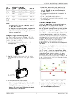
1.
Locate the notch in the upper left corner next to the
mounting magnet.
2.
Insert the black base of the attachment into the notch so
that the base clips onto the corner of the logger as shown
below.
Follow these guidelines when using a light pipe:
•
Make sure the end of the light pipe is as close to the light
source as possible.
•
Avoid 90-degree bends. The light pipe is flexible and can
be bent to gain access to hard-to-reach areas, but should
not have any sharp, 90-degree bends.
•
Maximize the signal strength on the logger LCD screen
by adjusting the light pipe while looking at the signal
bars (see
Calibrating the Light Sensor
for more details
on signal strength).
•
Be sure to secure the light pipe after the signal has been
optimized.
•
Do not support the logger by the light pipe.
•
Be sure that the pipe is seated all the way into the bracket
before deployment.
Calibrating the Light Sensor
Each time you place the logger in a new lighted environment,
you should calibrate it to the light level that you will be
monitoring. This ensures the logger is accurately determining
when the light changes between ON and OFF states. There are
two calibration methods available: auto-calibration (button
calibration) or preset calibration via HOBOware.
Auto-calibration is used to calibrate the ON and OFF threshold
of the logger to achieve reliable readings in an environment
where ambient conditions are unknown prior to deployment or
where logger light levels are variable.
In the auto-calibration
process, the light is measured via a built-in analog-to-digital
converter and the resulting value is used to generate a
calibration threshold.
Note:
Auto-calibration (button
calibration) must be done at the location where the logger will
be deployed.
Preset values are used when light levels are known in advance
and deployment speed is critical.
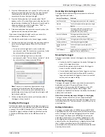
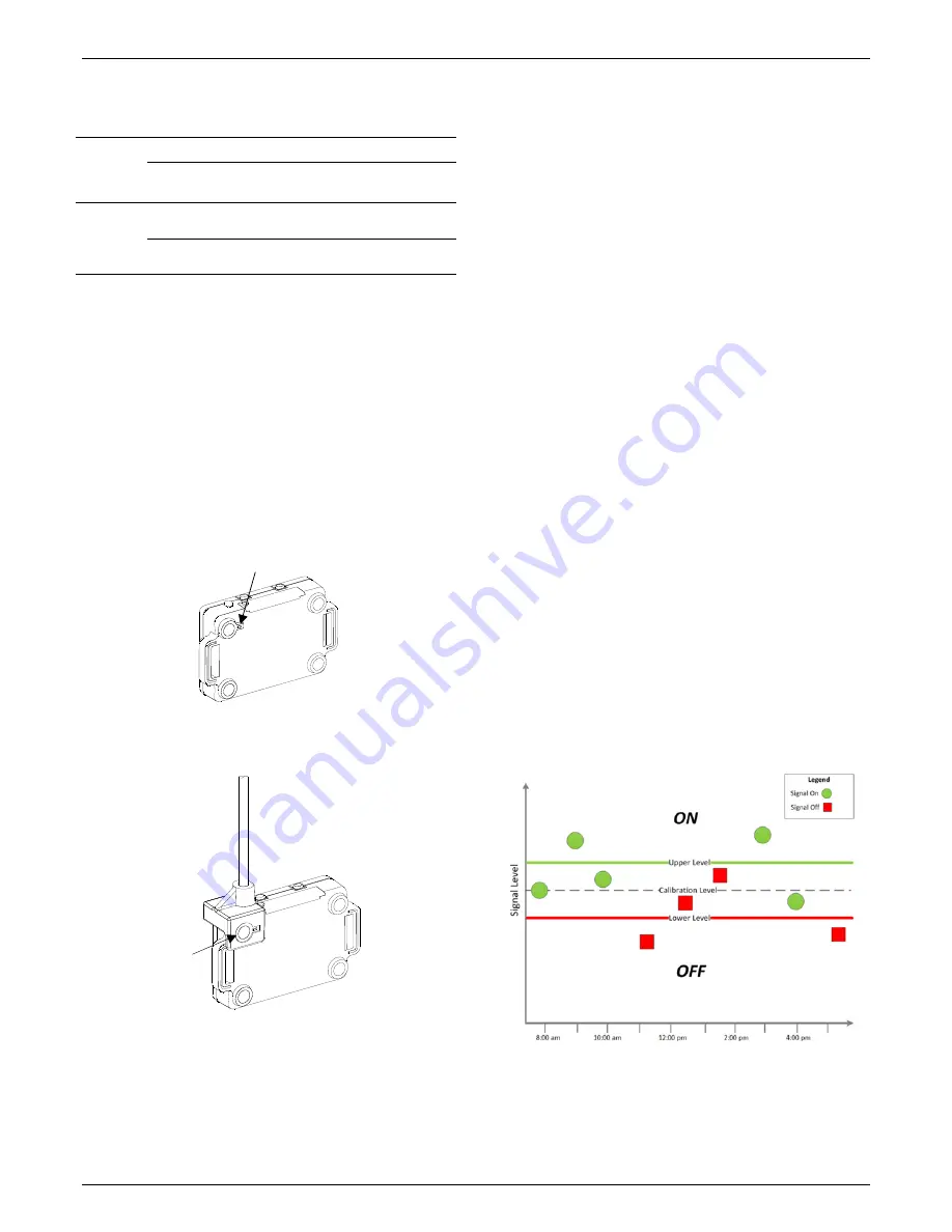
The logger has a built-in hysteresis level of approximately
±12.5% to prevent the sensor from toggling between ON and
OFF when the light level is near the calibration threshold. This
plot shows how the logger handles hysteresis. The logger
interprets the signal, or light, as ON until it drops below the
lower level of the calibration threshold. Once it switches to off,
the signal will not switch back to ON until it bypasses the upper
limit of the calibration level.
When auto-calibrating from the logger (button calibrating):
1.
After launching, deploy the logger near the light source to
be monitored and turn the light source on.
Notch on back of logger
Base of attachment
inserted into notch
Distributed by MicroDAQ.com, Ltd. www.MicroDAQ.com (603) 746-5524


