may damage the meter and expose the operator to a shock
hazard. Always recognize the meter voltage limits as stated on
the front of the meter.
z
Never apply voltage or current to the meter that exceeds the
specified maximum:
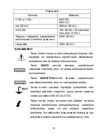
Input Limits
Function Maximum
Input
V DC or V AC
600VDC,
600V AC
mA DC/AC
400mA DC/AC
A DC/AC
10A DC/AC (30 seconds
max every 15 minutes)
Frequency,Resistance,
Capacitance,Duty Cycle, Diode
test, Continuity
250V DC/AC
Temperature 250V
DC/AC
SAFETY SYMBOLS
3
eter.
jury.
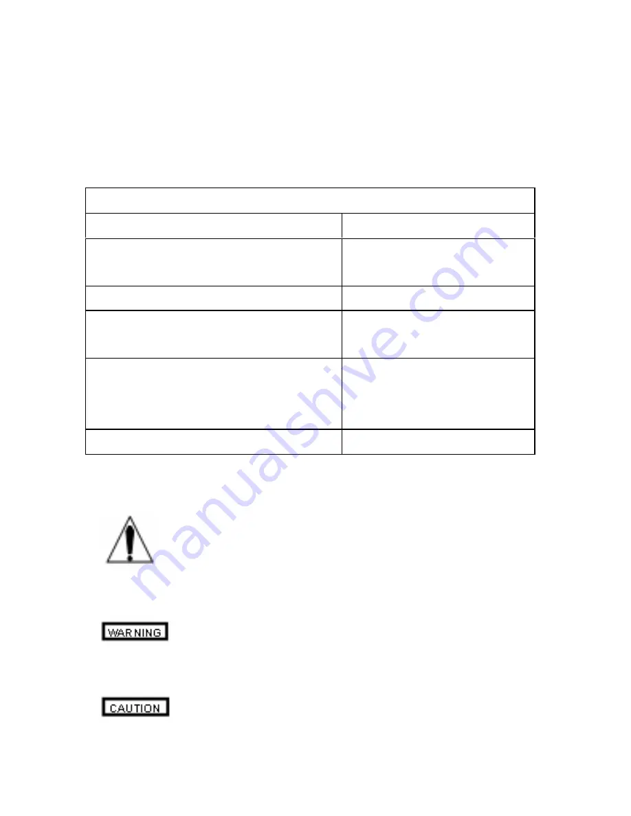
This symbol adjacent to another symbol, terminal or
operating device indicates that the operator must
refer to an explanation in the Operating Instructions to
avoid personal injury or damage to the m
This
WARNING
symbol indicates a potentially
hazardous situation, which if not avoided, could
result in death or serious in
This
CAUTION
symbol indicates a potentially
hazardous situation, which if not avoided, may result
Summary of Contents for DT-916N
Page 1: ...1...
Page 122: ...Russian DT 916N z z z z 60 30 122...
Page 123: ...z z z 600 600 A 400 A A 10A 30 15 250 250 123...
Page 124: ...500 124 MAX...
Page 125: ...1 2 3 10A 10A 125 4 COM 5 6 MODE 7 8 9 10 DATA HOLD BAT AUTO AC DC EN61010 1 2 CATIII 600...
Page 127: ...127 1 30 2 OL MODE...
Page 128: ...128 1 RANGE AUTO 2 RANGE 3 RANGE DATA HOLD 1 DATA HOLD HOLD 2 DATA HOLD HOLD 1 HOLD HOLD...
Page 129: ...1 RELATIVE REL 2 3 RELATIVE 129 1 2 1...
Page 130: ...130 1 V DC 2 COM V 3 4...
Page 131: ...131 240 0 1 V AC 2 COM V 3 4...
Page 132: ...132 10 30 30 1 COM 2 4000 A A A 3 400 A A A 4 10A 10A 5 DC 6 7 8 9...
Page 133: ...133 250 10A 30 1 COM 2 4000 A A A 3 400 A A 4 10A 10 5 6 7 8 9...
Page 134: ...1 2 COM 3 4 1 2 COM 134...
Page 135: ...3 MODE 4 5 150 1 2 MODE 3 COM 4 5 6 A OL B OL C 0 135...
Page 136: ...1 FREQ 2 COM F 3 4 1 nF 2 COM CAP 136...
Page 137: ...137 3 1 TEMP 2 COM Temp 3 30 4 5...
Page 138: ...138 1 BAT 2 3 1 2 3...
Page 139: ...139 1 2 3 4 5 0 5A 250 400 A 10A 250 10A 6...
Page 140: ...140 140...


