ACM5504-5-GV-I Quick Start (520040-Rev 1.3)
Page 1
ACM5504-5-GV-I
Quick Start Guide
Thank you for purchasing the ACM5504-5-GV-I management gateway. This Quick Start
walks you through installation and configuration. More details are available in the
User
Manual
which can be downloaded from
http://opengear.com/documentation
.
Step1 Check kit contents
ACM5504-5-GV-I device. E
xternal rack and DIN rail m
ount
tabs. G
reen connector block and
3G antenna. UTP cables.
Straight (319014) & crossover (319015) DB9F-RJ45S.
Straight (319016) DB9M-RJ45. Quick Start. 12VDC power
pack.
Step 2 Configure the hardware
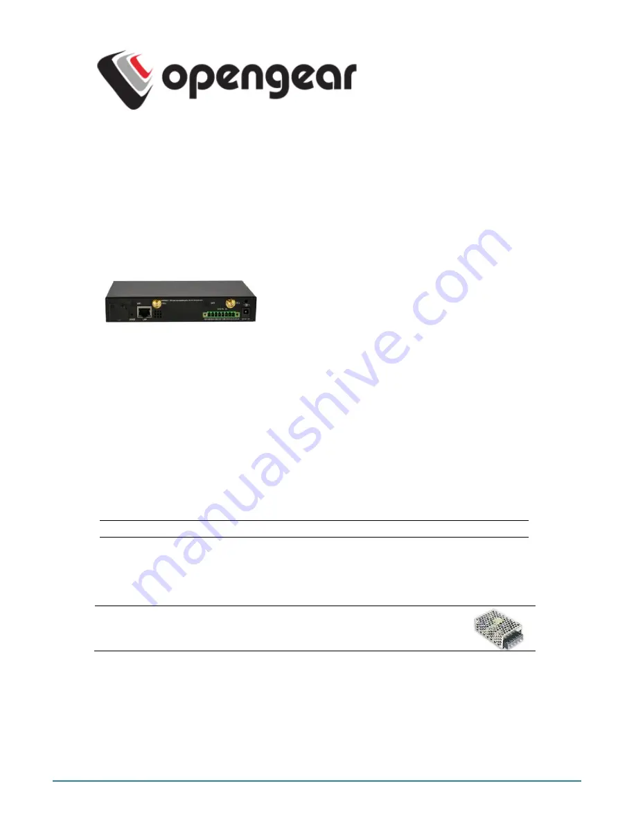
Attach rubber feet to base. Also attach the desired mounting tab and screw the
3G antenna on to the main
Cell (M)
connector If you have purchased a diversity
or GPS antenna, screw it on to Cell A
Connect the Ethernet
LAN
port to your network. Connect your management LAN
devices to the
ETHERNET 1-4
ports
Plug your serial console devices into
SERIAL 1-4
(all Cisco RJ45 pin-out).
Connect your USB devices to the two
USB
ports
Plug in the green screw terminal block and attach external sensors and DIO
Note:
Refer to ACM5500-I Addendum for RS422/485 and DIO details
Apply power
.
The ACM5504-5-GV-I can now be powered externally by either:
connecting the provided external power pack to the
12VDC
barrel socket or
connecting an external 9 to 24 VAC source to the
12VDC
barrel socket or
conn9V to 30 VDC to
DC PWR
and
GND
on the green terminal block
Note:
If you ordered the -SDC option you’ll have an external DC-DC
power converter (input v/- 36V DC to 72V DC. The
converter power cable/ connector plugs into the
12VDC
socket
The ACM5504-5-GV-I is ready for activation when the PWR status LED on the front panel
of the unit is lit steady, and the H/B (heartbeat) LED is flashing.
Step 3 Set up the appliance
The default IP Address is
192.168.0.1
(subnet mask
255.255.255.0
). With a web browser
on any computer that is network connected to the ACM5504-5-G-I:


