background image

 INSOMNIAC CIA Individual Unit Alarm 

Installation Manual 

P/N CIA-A96 

Revision 2 

Date Code: 1-22-2020 

Summary of Contents for INSOMNIAC CIA

Page 1: ...INSOMNIAC CIA Individual Unit Alarm Installation Manual P N CIA A96 Revision 2 Date Code 1 22 2020 ...

Page 2: ...OWER COATED 2 COMMUNICATIONS RS485 OR WIRELESS 900 MHZ 3 FORM C RELAY OUTPUTS 1 4 SECURE COMMUNICATIONS YES 5 TAMPER YES 6 MAX OPERATING VOLTAGE 24VDC 7 MIN OPERATING VOLTAGE 12VDC 8 MAX INPUT CURRENT 250 mA 12 VDC 125 mA 24VDC 9 OPERATING TEMP RANGE 31 TO 150 DEG F 10 HUMIDITY 0 95 NON CONDENSING 11 INGRESS RATING OUTDOOR EQUIPMENT ...

Page 3: ...A96 01 CIA Hardwired Unit Alarm Circuit Board Only CIA A96 02 CIA Hardwired Unit Alarm Enclosure The INSOMNAIC CIA Hardwired Individual Unit Alarm can be used in new construction or can be used to upgrade older individual unit alarms For instructions on upgrading older systems see Section XX of this manual WARNING Be sure data is pulled only from RS485 channel 2 WARNING Do not pull power from RS48...

Page 4: ...A Individual Unit Alarm Installation Manual Rev 2 4 INSTALLATION Physical Installation and Mounting This document contains instruction on installing the INSOMNIC CIA Individual Unit alarm system Figure 1 ...

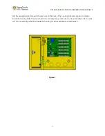
Page 5: ... in the back pane If the enclosure is being mounted on a wall before mounting run a bead of silicone in a square around the back of the enclosure about inch from the edge Also from the inside seal around each screw hole and the wire entry hole with an outdoor silicone sealant after pulling the wires through Figure 2 ...

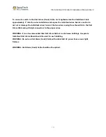
Page 6: ...s through the wire hole on the back of the housing Allow ample wire to remain inside the housing After the wire connections are complete excess wire can be pushed back into the wall or it can be carefully positioned inside the housing for future maintenance and service Figure 3 ...

Page 7: ...ote All installations must conform to local building and electrical codes and shall be in accordance with the Nation Electric Code ANSI NFPA 70 When discrepancies exist between local codes and this manual local code takes precedence RS485 communication cables entering the enclosure should be insulated and shielded with drain wires connected Figure 4 ...

Page 8: ...2 3 4 5 6 7 8 9 1 0 1 1 1 2 1 3 1 4 1 5 1 6 Gn d Gn d Gn d Gn d Punch Down Connector 2 C h C h C h C h C h C h C h C h C h C h C h C h C h C h C h C h Gn d Gn d Gn d Gn d 1 7 1 8 1 9 2 0 2 1 2 2 2 3 2 4 2 5 2 6 2 7 2 8 2 9 3 0 3 1 3 2 Gn d Gn d Gn d Gn d Punch Down Connector 3 C h C h C h C h C h C h C h C h C h C h C h C h C h C h C h C h Gn d Gn d Gn d Gn d 3 3 3 4 3 5 3 6 3 7 3 8 3 9 4 0 4 1 4 ...

Page 9: ... com product 206 ams 37 series QuickSwitch can be used on both roll up and swing doors if the door latch is made of ferrous metal and is long enough to go all the way through the door switch Recessed switches such as the Amesco AMS 21 https www pottersignal com product 246 ams 21 series or the Amseco AMS 26 https www pottersignal com product 282 ams 26 series can be used for swing doors UNIT ALARM...

Page 10: ...cut or damage the individual wires Connect the two wires coming from the switch to the Unit Alarm Cable using UG style connectors to the proper wires WARNING It is not recommended that Unit Alarm Cable is run between buildings A separate Individual Unit Alarm Board should be used for each building WARNING Do not run Unit Alarm trunk Cable with unshielded AC power lines or near light fixtures WARNI...

Page 11: ...ctions apply 1 Strip back the outer insulation and shield foil from both of the 18 AWG 4 conductor shielded cables coming from the Gateway or previous device in line and going out to the next device in line being careful not to cut the bare shield wire Strip inch of insulation off the end of each of the individual colored conductor wires 2 Remove the terminal blocks from the door alarm circuit boa...

Page 12: ...re provided to show if the relay is activated Typical sirens and strobes require a normally open contact RELAY CONTACT RATINGS Item Rating Contact Type Single Ag Alloy Cd Free Rated Load 5A NO 3A NC 30VDC Max Switching Voltage 30VDC Max Switching Current 5A NO 3A NC Warning Wiring the relay to the operating device will introduce the operating device control voltage into the Individual Unit Alarm h...

Page 13: ...the unit Remove dirt or dust that has collected on the inside of the housing and the circuit board that could cause problems Note any signs of water damage or corrosion caused by a leak in the enclosure seals Replace any worn seals A small can of compressed air can be used to remove insects and dust from the circuit board NOTICES and DISCLAIMERS Liability Disclaimer While every effort has been mad...

Page 14: ... should be used to document the wire color that the switch is connected to Channel Unit Switch Gnd Cmn Channel Unit Switch Gnd Cm 1 49 2 50 3 51 4 52 5 53 6 54 7 55 8 56 9 57 10 58 11 59 12 60 13 61 14 62 15 63 16 64 17 65 18 66 19 67 20 68 21 69 22 70 23 71 24 72 25 73 26 74 27 75 28 76 29 77 30 78 31 79 32 80 33 81 34 82 35 83 36 84 37 85 38 86 39 87 40 88 41 89 42 90 43 91 44 92 45 93 46 94 47 ...

Page 15: ...ntation The alarm alm is a CSV file with the format of Unit Mux Channel Status where Status is 0 Alarm Off or 1 Alarm On 1 Export the Alarm Alm file from the StorLogix or Falcon 2000 software 2 Document the existing PTI Door Alarm Mux address and location The PTI Alarm Mux address can be found by looking at the DIP switches settings on the Mux This mux number will be used when importing the alarm ...

Page 16: ...dual unit alarms are working properly and the proper units are being reported when the unit door is opened or closed If the current system is not operational then it is recommended that these issues are corrected before proceeding To speed configuration of the system the INSOMNIAC CIA has the ability to import the unit mux channel configurations a CSV file 1 Export the Mux Slot report In the DigiG...

Page 17: ...larm wires to the punch down connectors 9 Reconnect the alarm relay if used 10 Connect RS 485 communication wires Data CMN and Data to the CIA A96 Circuit Board Refer to Figure 4 Ensure that the connections are terminated correctly 11 Connect DC and DC to the CIA A96 Circuit board IMPORTANT If the device is being powered by a separate 12V power supply the power wires CAN NOT be connected to the Ga...

Reviews: