Free To Air / Common Interface Digital Satellite Receiver
HARDWARE DESCRIPTION
7
Free To Air / Common Interface Digital Satellite Receiver
HARDWARE DESCRIPTION
6
1) POWER : This key is used to turn the receiver on and off (stand by).
2) CH : These keys are used to change the channels.
3) VOL : These keys are used to increase and decrease the volume
level manually.
4) INFRARED SENSOR : This is to receive the IR commands from the
RCU. Do not block the view of the sensor.
5) 7 SEGMENT DISPLAY : This SEGMENT display will show the current
channel number.While the receiver is in stand by mode, the display will show
the current time.
7) CI CAMSLOTS : 2 Slots for Common Interface CAM (VIACCESS,
IRDETO, NAGRAVISION, CRYPTOWORKS, CONAX, SECA) with smart
card.(Option for CI model only)
POWER
C H
VOL
INFRARED SENSOR
7 SEGMENT DISPLAY
CI CAM SLOTS
6) LED DISPLAY: This LED display will show the current power mode status.
If receiver is in stand by mode,stand by mode LED will be on. and when
receiver is in on mode, on mode LED will be on.
(Option for LED display model only)
LED DISPLAY
STANDBY
ON
8) SMART CARD INTERFACESLOTS : To watch scrambled
channels you should insert a smart card into Smart Card Interface issued the
service provider whom you subscribes to. Therefore you can watch only a
specific range of channels with entitlements in smart card. The smart card
includes information to decipher parameters necessary for descrambling the
program. Please note that the gold chip on the smart card should face
download and inward when you insert when you insert it into Smart Card
Interface. (Option for CAS model only)
SMART CARD
INTERFACESLOTS
4. A. FRONT PANEL
4. HARDWARE DESCRIPTION
③
②
⑦
⑥
⑧
⑩
⑨
⑤
④
①
LNB IN
IF OUT
SERIAL PORT
VCR
SPDIF
R
TV
VIDEO
AUDIO L
TV OUT
ANT IN
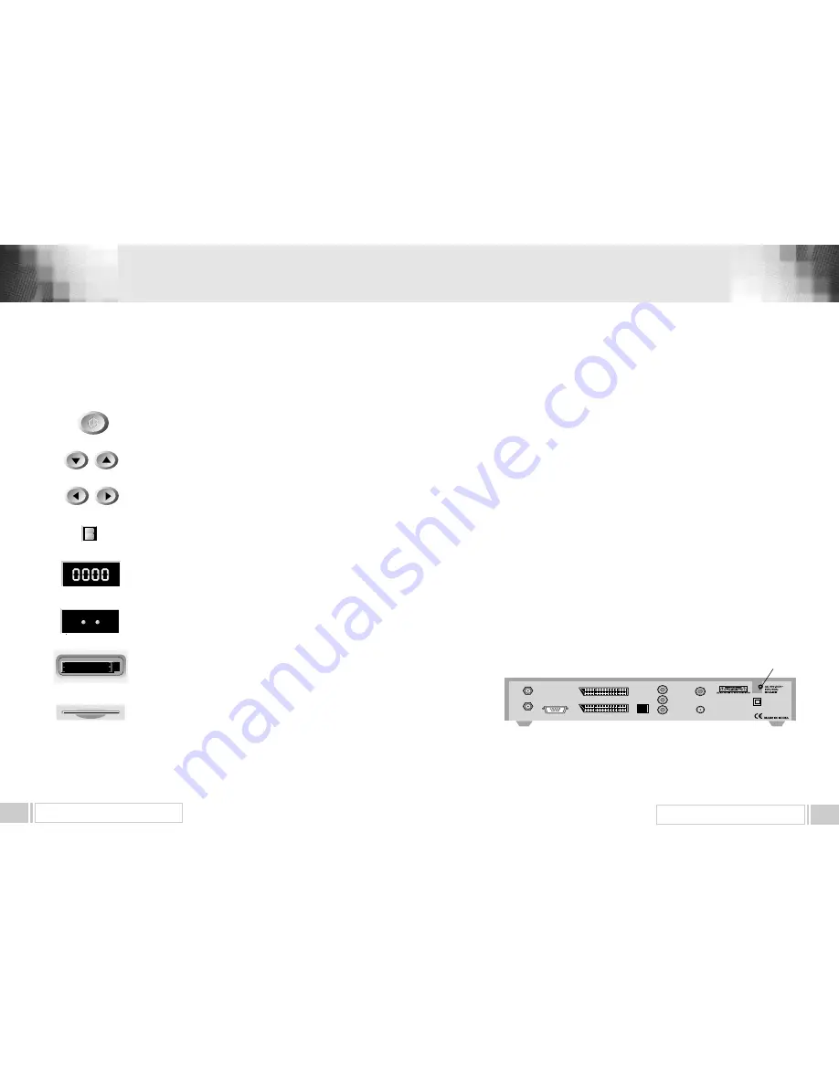
1) LNB IN : This port is to connect the coaxial cable from LNB of your Dish. The IF input is provided through
this port and the input frequency range is 950
�
2150MHz. Also the voltage switching 13V and 18V is
passed through this port.
2) IF OUT : To enable the connection of an analog receiver, The receiver is provided with this port. Connect
this port to LNB IN port of the other receiver via RF Cable.
3) SERIAL PORT : This is used to connect your receiver with computer through a serial cable.
This port can be used for upgrading software.
4) TV SCART : This is used to connect your TV through SCART.
5) VCR SCART : This is used to connect your VCR.
(When you connect external sets to above two SCART sockets, always use fully featured SCART cables)
6) S/PDIF DIGITAL OUTPUT : This port is for the connection to the exterual Hifi system which has a optical
S/PDIF input interface. (Option)
7) VIDEO, AUDIO R/L : These RCA connectors are used to connect any external video and audio.
8) ANT IN : This is used to connect your local RF channels to your TV through Loop.(Option)
9) TV OUT : This is used to connect your TV through RF cable.(Option)
10) POWER INPUT : This is to plug in the AC mains power cord.
The input AC volts range is 90V to 240V, 50Hz/60Hz supply.
4. B. REAR PANEL


