background image

© 2014, 2015, 2018 OPEX

®

 Corporation

All rights reserved. This document is provided by OPEX for use by their customers, partners, and dealers. No portion 
of these materials may be reproduced, published, or stored in a database or retrieval system, other than for its in-
tended use without the express, written permission of OPEX Corporation.

March 15, 2018

Document Revision 18-01

Falcon Transportable Manual

Summary of Contents for Falcon Transportable

Page 1: ...their customers partners and dealers No portion of these materials may be reproduced published or stored in a database or retrieval system other than for its in tended use without the express written...

Page 2: ...rhaul of manual Overview and On site Travel split into their own sections to avoid errors from duplicate information On site Travel modified for new front travel support Loading into a Vehicle has not...

Page 3: ...7 Recommended Items 7 Chapter 2 Breakdown Remove Secondary Items 10 Collapse the Frame 11 Chapter 3 On site Travel Travel Safety and Precautions 14 About Travel Supports 14 Ramp Warning 15 Optional Co...

Page 4: ...le Manual OPEX Corporation Chapter 5 Unloading Removal from the Vehicle 32 Chapter 6 On Site Setup Desk Setup 38 Extending the Desktop 39 Bins and Trays 41 PC Electrical Setup 42 Optional Computer Tra...

Page 5: ...Falcon Transportable Manual Overview Reference Diagram 6 Deployed Dimensions 7 Stored Dimensions 7 Required Items 7 Recommended Items 7...

Page 6: ...bins b Bypass bin c Left leg height adj crank d Front loading wheels e Left leg support f Optional computer tray g Travel supports h Right leg support i Rear loading wheels j Crank handle storage k Ri...

Page 7: ...ed so that no tools are required for taking it from one site to another However you will need a means of safely securing the Falcon inside the vehicle Due to the variation among vehicles Opex cannot s...

Page 8: ...8 Overview Falcon Transportable Manual OPEX Corporation...

Page 9: ...Falcon Transportable Manual Breakdown Remove Secondary Items 10 Collapse the Frame 11...

Page 10: ...nveyor with a blanket or piece of foam underneath it to protect the screen Remove the stacker and bypass bins On the back of the machine slide the clear cable support in against the rear of the machin...

Page 11: ...and remove the right side cover 2 Take all removed components to the vehicle This includes the PC UPS keyboard mouse cables bins and right side cover Collapse the Frame Release the horizontal locking...

Page 12: ...guideline this is usually high enough that the right loading wheels are level to the leg base s top trim Continue to On site Travel on page 13 for safety information and instructions on connecting th...

Page 13: ...Transportable Manual On site Travel Travel Safety and Precautions 14 About Travel Supports 14 Ramp Warning 15 Optional Computer Tray 15 Connecting the Travel Supports 16 Disconnecting the Travel Suppo...

Page 14: ...hen taking it to and from a vehicle or from a fully deployed position if you are only moving it to another room in the same building CAUTION CAUTION The travel supports are required any time the Falco...

Page 15: ...are often sloped which can allow the Falcon to ride up and risk tipping Optional Computer Tray Do not move the Falcon Transportable outside with the computer tray option deployed Keeping the tray dep...

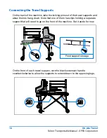
Page 16: ...of the travel supports and allow them to hang down Note that one of them has clips holding a separate support that will need to go on the front of the machine Set it aside for now On the front of eac...

Page 17: ...ball connector in the back of the left leg The top left bottom right travel support has a secondary arm that can swing forward Turn it toward the connector closer to the middle of the leg then press t...

Page 18: ...oyed Falcon for movement within the same building In this case put it back in its holding clips on the top right bottom left support at the rear of the machine Turn the travel supports black handles c...

Page 19: ...the top of each foot to retract it off of the floor The Falcon is now ready to be taken to a vehicle or work site Once it has arrived see Disconnecting the Travel Supports on page 20 and then For load...

Page 20: ...l Supports Disconnect each of the ball and socket joints at the legs corners There are 5 of these connections total On the top left bottom right travel support push the swing arm s button 1 and collap...

Page 21: ...ndles Place the front travel support into the clips on the top right bottom left support Fold and pin the travel supports into their stored positions behind the Falcon desktop The Falcon Transportable...

Page 22: ...22 On site Travel Falcon Transportable Manual OPEX Corporation...

Page 23: ...Falcon Transportable Manual Loading into a Vehicle Inserting and Collapsing the Falcon 24 Tie Down Requirements 28 Anchor Points 29...

Page 24: ...e Falcon Retract the travel supports Disconnecting the Travel Supports on page 20 Take the pins out of the front loading wheels and extend them into the raised position Replace the pins to lock the wh...

Page 25: ...retract the left leg so that the Falcon s weight is supported by the front loading wheels from inside the vehicle Remove the pin from the left leg s support 1 Raise the lever off of the top surface 2...

Page 26: ...w This will prevent the leg from locking itself back into the deployed position when you attempt to push it into the vehicle Roll the Falcon further into the vehicle so the left leg s wheels are insid...

Page 27: ...support s clamp 1 then open it by pushing the handle to the front 2 Fold the right leg support back against the leg 3 then lock it in place 4 Unlock the lower pin at the right rear corner Lift the ri...

Page 28: ...teria The tie down method used should prevent movement on all three axes side to side front to back and up and down Tie down locations on the vehicle must be strong stable areas on the floor The Falco...

Page 29: ...Loading into a Vehicle 29 Falcon Transportable Manual OPEX Corporation Anchor Points Right side desktop s mounting holes are NOT anchor points Anchor point Do not use Back Front...

Page 30: ...30 Loading into a Vehicle Falcon Transportable Manual OPEX Corporation...

Page 31: ...Falcon Transportable Manual Unloading Removal from the Vehicle 32...

Page 32: ...e vehicle Pull the end of the Falcon s right leg until its base slides out of the collapsed position and to the end of the frame Allow the leg to hang outside the vehicle In the right rear corner use...

Page 33: ...t on the frame then apply the clamp over the post 3 Insert the clamp s pin to lock it in place 4 Use the crank handle clockwise to extend the right leg Raise the Falcon Transportable high enough that...

Page 34: ...ift up before it will move Pull the Falcon further out so that the left leg hangs freely but the front loading wheels still support it from inside the vehicle Straighten the left leg so its support en...

Page 35: ...vehicle Adjust the height of each leg so the machine is approximately level and at a height that is comfortable for you to push Take the 2 pins out of the front loading wheels frame so it can hang do...

Page 36: ...36 Unloading Falcon Transportable Manual OPEX Corporation...

Page 37: ...Falcon Transportable Manual On Site Setup Desk Setup 38 Extending the Desktop 39 Bins and Trays 41 PC Electrical Setup 42 Optional Computer Tray 42 Connections 43...

Page 38: ...d in multiple locations on the site disconnect the front travel support and the front portion of the top left bottom right travel support This will allow use of the cable ties noted on page 42 Note Wi...

Page 39: ...he Falcon release the upper locking pin Pull the right side of the Falcon to extend it to its deployed length If the Falcon you are using is the short version skip this step Re engage the locking pin...

Page 40: ...o the cover is level and push it left against the main desktop The transition cover and front cover each have a lip that is meant to fit underneath the right side cover Adjust the cover s position as...

Page 41: ...ass bins The stacker bins positions are Top Side justifiers on top and bottom Middle Side justifiers on bottom only Bottom No side justifiers On the back of the machine extend the clear cable support...

Page 42: ...o the right and buckle them down with the supplied strap Refer to the connections diagram on the next page If the Falcon will be used in multiple areas within the same building use the supplied cable...

Page 43: ...Note Colors applied to the wires in this diagram are only for visibility and do not have any special meaning FALCON REAR PANEL UPS Battery backup Surge only AC Power In Not used Top CIS High speed lin...

Page 44: ...44 On Site Setup Falcon Transportable Manual OPEX Corporation...

Reviews: