background image

150

Statistics

Sure Sort™ Operator Manual

OPEX Corporation

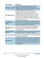
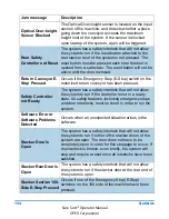
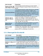
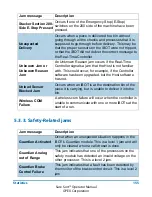
 5.3.2. Jams

The .csv file will only display jams that occurred during the selected time range 
in your report. The following is a list of all possible jams.

Jam message

Description

Charging rail 
sensor(s) blocked

Each charging rail in the machine (except the one on 
the main door) has sensors behind it to detect if the 
rail is extended or retracted. The Real-Time Controller 
calls a jam if the extended sensor or retracted sensor 
is blocked when it should not be. The extended 
sensor will be blocked when the machine is in an idle 
or stopped state and the iBOTs are parked. It will be in 
a retracted state when the machine is running and the 
iBOTs are moving through the column.

Critically low iBOT 
power

Occurs when the Real-Time Controller detects that 
the power level of an iBOT is too low to deliver the 
piece, as it does not have enough power to spin the 
conveyor and then return to the charge rail.

Critical Message 
Failure

Occurs when the Real-Time Controller has not 
received confirmation that the iBOT has received a 
critical message. This occurs when the iBOT is 
approaching the loading point.

ELC 
Communication 
Error

caused when the Host application loses 
communication with the External Link Component 
(ELC). 

Loss of communication with the ELC can result in one 
or more critical messages being lost by the Host 
application or the ELC, and they may now have 
conflicting data about pieces in the system. Therefore, 
the job is not allowed to proceed even if 
communication can be reestablished with the ELC. 
The correct disposition of pieces that are in the 
system, but not yet delivered, needs to be determined.

Summary of Contents for Sure Sort

Page 1: ...e dans une base de données ou un système de récupération sauf pour l usage auquel elle est destinée sans le consentement exprès et écrit d OPEX Corporation Novembre 2019 Sure Sort Manuel de l opérateur AVERTISSEMENT Lisez attentivement ce manuel avant d essayer d utiliser cet équipement Conservez une copie à jour pour référence 9166900OM FR Révision 19 08 Traduction des instructions originales Sur...

Page 2: ...eproduced published or stored in a database or retrieval system other than for its intended use without the express written consent of OPEX Corporation November 2019 Sure Sort Operator Manual WARNING Read this manual thoroughly before attempting to operate this equipment Keep a current copy for your reference 9166900OM EN Revision 19 08 Original Instructions Sure Sort ...

Page 3: ...duit voir Emplacements du numéro de série du matériel à la page 109 Pour les autres demandes OPEX Corporation 305 Commerce Dr Moorestown NJ 08057 4234 États Unis Tél 1 856 727 1100 Fax 1 856 727 1955 https www opex com Si vous trouvez des erreurs imprécisions ou tout autre problème ou préoccupation dans ce document veuillez contacter les rédacteurs techniques OPEX par courriel à GroupTechwriters o...

Page 4: ...serial number of the product ready see Equipment Serial Number Locations on page 109 For other inquiries OPEX Corporation 305 Commerce Dr Moorestown NJ 08057 4234 USA Tel 1 856 727 1100 Fax 1 856 727 1955 https www opex com If you find errors inaccuracies or any other issues or concerns with this document please contact the OPEX Technical Writers via email at GroupTechwriters opex com For help wit...

Page 5: ...nisation électrique industrielle UL 61800 5 1 iBOT uniquement Norme des systèmes de moteurs électriques à vitesse ajustable Consignes de sécurité électrique thermal et énergétique 7 0 Approbation Je le la soussigné e déclare par la présente que l équipement spécifié ci dessus est conforme aux directives et normes susmentionnées Lieu d émission Moorestown NJ États Unis Date de parution 19 février 2...

Page 6: ...dling equipment and systems Safety and EMC requirements for equipment for mechanical handling of unit loads EN ISO 12100 2 2003 Safety of machinery Basic concepts general principles for design Part 2 Technical principles EN 60204 1 2006 A1 2009 Safety of machinery Electrical equipment of machines General requirements ETSI EN 300 328 V2 1 1 2016 11 Wideband transmission systems Data transmission eq...

Page 7: ...e pour mentionner Tirez le E stop pour désactiver était tourné Étape 8 ajoutée redémarrer le hôte Page 69 Section 2 7 Procédures LOTO mises à jour appareil de verrouillage EU ajouté procédure relative au dispositif de verrouillage de la prise placée dans un section distincte interrupteur de verrouillage changé pour la poignée du sectionneur principal étapes de restauration de l énergie déplacées d...

Page 8: ...0 200 to match S W diagnostics Page 63 step 7 revised to state pull up E stop to deactivate was twist Added step 8 restart host Page 69 Section 2 7 LOTO procedures updated added EU lockout device plug lockout device procedure placed in separate section lockout switch changed to main disconnect switch handle power restoration steps moved to separate section Page 86 90 iBOT images updated Page 99 BT...

Page 9: ...l emplacement S N arrière du iBOT 19 05 22 avril 2019 Manuels traduits uniquement Omission de la Section 2 3 version française des Consignes de sécurité requises enAmérique du Nord 19 06 Le 10 mai 2019 Page 29 section ajoutée Étiquette de caractéristiques Numéro de série suite étiquettes pour le Japon Page 22 et 38 ajout des étiquettes d avertissement d arc électrique Page 48 et 59 ajout de l étiq...

Page 10: ...09 Corrected description of iBOT rear S N location 19 05 Apr 22 2019 Translated manuals only Section 2 3 French Safety Guidelines required for North America omitted 19 06 May 10 2019 Page 29 added section Ratings Serial Number labels continued labels for Japan Page 22 and 38 added Arc Flash warning labels Page 48 and 59 added radio compliance label for Japan Page 69 LOTO procedures updated to incl...

Page 11: ...agega rantit l arrêt des iBOT Page 81 Ajout enlever le signe de attention 19 08 16 septembre 2019 Page 7 Ajout du tableau d historique de traduction Page 27 Mise à jour de l étiquette du courant de fuite élevée Page 31 Ajout de l étiquette de risque d électrocution alimentations électriques Page 41 et 52 étiquette de risque d écrasement mise à jour Page 49 étiquette de numéro de série ajoutée Page...

Page 12: ...ing statement Page 78 Clarified step 5 interlock delay ensures iBOTs stopped Page 81 Added remove caution sign 19 08 Sep 16 2019 Page 7 Translation history table added Page 27 updated high leakage current label Page 31 added shock hazard label power supplies Page 41 and 52 updated crush hazard label Page 49 added serial number label Page 51 updated shock hazard label location Page 55 59 and 110 up...

Page 13: ...s 2019 DE01 Version initiale allemand 19 05 Mai 2019 IT01 JA01 PL01 Version initiale italien japonais polonais 19 07 Mai 2019 DE02 Voir Historique du document 19 08 Sept 2019 JA02 Page 3 Mise à jour du DoC Pour toute autre modification consulter l Historique du document 19 08 Oct 2019 KO01 Version initiale coréen 19 08 Oct 2019 PL02 Voir Historique du document 19 08 Nov 2019 FR01 Version initiale ...

Page 14: ...age 19 03 Mar 2019 DE01 Initial release German 19 05 May 2019 IT01 JA01 PL01 Initial release Italian Japanese Polish 19 07 May 2019 DE02 See Document History 19 08 Sept 2019 JA02 Page 3 Updated DoC All other changes see Document History 19 08 Oct 2019 KO01 Initial release Korean 19 08 Oct 2019 PL02 See Document History 19 08 Nov 2019 FR01 Initial release French DE German ES Spanish FR French IT It...

Page 15: ...age du module d empilage de base et d extrémité 39 2 3 5 Étiquetage du module d expansion 50 2 3 6 Étiquetage du iBOT 55 2 3 7 Informations sur le condensateur de haute capacité 60 2 4 Arrêts d urgence et interrupteurs de sécurité 61 2 4 1 Boutons d arrêt d urgence E Stops 61 2 4 2 Système de verrouillage 64 2 4 3 Poignée de sortie d urgence 66 2 4 4 Boutons de réinitialisation 67 2 5 Tour de phar...

Page 16: ... 3 Scan tunnel labels 36 2 3 4 Base and end stacker module labels 39 2 3 5 Expansion module labels 50 2 3 6 iBOT labels 55 2 3 7 Ultracapacitor product information 60 2 4 Emergency stops and interlock switches 61 2 4 1 Emergency stop buttons E Stops 61 2 4 2 Interlock system 64 2 4 3 Emergency Exit Handle 66 2 4 4 Reset Buttons 67 2 5 Light Tower 68 2 6 Lockout Tagout LOTO Procedures 69 2 6 1 What...

Page 17: ...ct ELC 93 3 3 3 Le tunnel de code barres OPEX optionnel 94 3 3 4 Scanner fixe 95 3 3 5 Fonction Pack to Light 95 3 3 6 Fonctionnalité du témoin d arrêt 96 3 4 Spécifications 97 3 4 1 Configuration de base 97 3 4 2 Manipulation matérielle articles en stock 97 3 4 3 Options 97 3 4 4 Dimensions du module 98 3 4 5 Spécifications environnementales 99 3 5 Dispositifs des équipements et Espace du pallier...

Page 18: ... ELC 93 3 3 3 The Optional OPEX Barcode Tunnel 94 3 3 4 Fix Mount Scanner 95 3 3 5 Pack to Light feature 95 3 3 6 Stop Light feature 96 3 4 Specifications 97 3 4 1 Basic Configuration 97 3 4 2 Material Handling inventory items 97 3 4 3 Options 97 3 4 4 Module Dimensions 98 3 4 5 Environmental specifications 99 3 5 Equipment Layout and Required Floor Space 100 3 6 Electrical Requirements North Amer...

Page 19: ...hôte 120 4 1 4 Naviguer dans le logiciel hôte 128 4 1 5 Détails de l écran d exécution 129 4 1 6 Onglets des informations 130 4 1 7 Élimination des bourrages 135 4 2 Bourrages liés au produit 139 4 3 Basculer entre le logiciel hôte et InductELC 142 Chapitre 5 Statistiques 5 1 Aperçu 144 5 2 Dresser des rapports 144 5 2 1 Paramétrer l intervalle de temps 145 5 3 Définitions de rejet et de bourrage ...

Page 20: ... Logging in to the Host software 120 4 1 4 Navigating the Host software 128 4 1 5 Run Screen details 129 4 1 6 Information tabs 130 4 1 7 Clearing jams 135 4 2 Product related jams 139 4 3 Toggling between the Host InductELC software 142 Chapter 5 Statistics 5 1 Overview 144 5 2 Creating Reports 144 5 2 1 Setting the Time Range 145 5 3 Reject and Jam Definitions 146 5 3 1 Rejects 146 5 3 2 Jams 15...

Page 21: ...Sure Sort Manuel de l opérateur 1 Introduction 1 1 À propos de ce manuel 12 1 1 1 Aides à la navigation manuelle 13 1 1 2 Conventions des messages de sécurité 14 ...

Page 22: ...Sure Sort Operator Manual 1 Introduction 1 1 About This Manual 12 1 1 1 Manual navigation aids 13 1 1 2 Safety message conventions 14 ...

Page 23: ...pour ces niveaux de compétence Employé affecté Un employé dont le travail lui impose d utiliser une machine ou un matériel dont l entretien ou la maintenance est effectué sous verrou ou blocage ou de travailler dans une zone où un tel entretien ou une telle maintenance est en cours d exécution Employé autorisé Une personne qui verrouille ou bloque les machines ou le matériel afin d y effectuer des...

Page 24: ...ill levels Affected Employee An employee whose job requires him or her to operate or use a machine or equipment on which the servicing or maintenance is being performed under lockout or tagout or whose job requires him her to work in an area in which such servicing or maintenance is being performed Authorized Employee A person who locks out or tags out machines or equipment in order to perform ser...

Page 25: ... pouvez cliquer ou appuyer pour aller directement à une page ou une adresse web donnée De plus vous pouvez cliquer ou appuyer sur tous les éléments dans la Table des matières ainsi que les signets dans la barre latérale du fichier PDF afin de naviguer directement vers une page particulière Assurez vous d utiliser la dernière version d Adobe Acrobat Reader pour des performances optimales Adobe et A...

Page 26: ...s you can click on or tap to go directly to a particular page or web address In addition all items in the Table of Contents as well as the bookmarks in the side bar of the PDF file can be clicked or tapped to navigate directly to a particular page Make sure to use the latest version of Adobe Acrobat Reader for optimal performance Adobe and Acrobat Reader are registered trademarks of Adobe Systems ...

Page 27: ...pitre 2 Sécurité DANGER Indique une situation dangereuse qui si elle n est pas évitée peut entraîner la mort ou des blessures graves L utilisation de ce mot de signalement est limitée aux situations les plus extrêmes AVERTISSEMENT Indique une situation dangereuse qui si elle n est pas évitée pourrait entraîner la mort ou des blessures graves ATTENTION Indique une situation dangereuse qui si elle n...

Page 28: ...t safety information in Chapter 2 Safety DANGER Indicates a hazardous situation that if not avoided will result in death or severe injury The use of this signal word is limited to the most extreme situations WARNING Indicates a hazardous situation that if not avoided could result in death or serious injury CAUTION Indicates a hazardous situation that if not avoided could result in minor or moderat...

Page 29: ...61 2 4 1 Boutons d arrêt d urgence E Stops 61 2 4 2 Système de verrouillage 64 2 4 3 Poignée de sortie d urgence 66 2 4 4 Boutons de réinitialisation 67 2 5 Colonne lumineuse 68 2 6 Procédures de verrouillage blocage LOTO 69 2 6 1 Qu est ce que le verrouillage blocage 69 2 6 2 Appareils de verrouillage blocage nécessaires 70 2 6 3 LOTO Entretien et réparation de la machine 72 2 6 4 Mettre l alimen...

Page 30: ...rlock switches 61 2 4 1 Emergency stop buttons E Stops 61 2 4 2 Interlock system 64 2 4 3 Emergency Exit Handle 66 2 4 4 Reset Buttons 67 2 5 Light Tower 68 2 6 Lockout Tagout LOTO Procedures 69 2 6 1 What is Lockout Tagout 69 2 6 2 Lock out Tag out devices required 70 2 6 3 LOTO Machine maintenance and repair 72 2 6 4 Fully de energizing AC power plug in machines 75 2 6 5 Fully de energizing AC p...

Page 31: ...stions de sécurité concernant le fonctionnement et la maintenance de l appareil OPEX décrit dans ce manuel Ce chapitre fournit une explication des conventions de sécurité utilisées tout au long de ce manuel ainsi que des consignes de sécurité à respecter lors de l utilisation de cet appareil AVERTISSEMENT Lisez attentivement ce chapitre avant d utiliser cet appareil ...

Page 32: ... various safety issues regarding the operation and maintenance of the OPEX equipment described in this manual This chapter provides an explanation of the safety conventions used throughout this manual as well as safety guidelines to be observed when working with this equipment WARNING Read this chapter thoroughly before using this equipment ...

Page 33: ...nsateurs reportez vous à la section Informations du produit sur l ultra condensateur à la page 60 Se tenir sous un iBOT Ne restez pas sous un iBOT lorsqu il transporte une charge Personne ne doit se tenir sous des iBOT qui transportent des charges Tenez les objets mobiles hors de portée des pièces mobiles exposées de la machine Les pièces mobiles de Sure Sort telles que le convoyeur peuvent se coi...

Page 34: ...apacitor safety refer to Ultracapacitor product information on page 60 Standing under an iBOT Do not stand under an iBOT while it is carrying a load No one may remain underneath iBOTS with loads Keep loose objects away from any exposed moving parts of the machine The moving parts of the Sure Sort such as the conveyor can become jammed and or damaged by foreign objects Keep hands hair loose clothin...

Page 35: ...doivent être nettoyés bloquez la pièce avec une manivelle pendant le nettoyage ou nettoyez la à l arrêt N utilisez pas d aérosol de gaz dépoussiérant inflammable et à haute pression pour retirer la poussière et les débris de la machine Familiarisez vous avec l emplacement des commutateurs d arrêt d urgence de la machine Les commutateurs d arrêt d urgence permettent un arrêt rapide de tous les mote...

Page 36: ...roller gate or similar part needs to be cleaned hand crank the part during cleaning or clean it while stationary Do not use flammable high pressure canned air to clean dust and debris from the machine Familiarize yourself with the location s of machine Emergency Stop switches The E Stop switches enable a quick stop of all motors in the machine in the event of an emergency involving potential perso...

Page 37: ...tiquettes graphiques uniquement pour l UE et diverses machines internatio nales sans texte Bien qu elles semblent différentes les étiquettes ont toutes un emplacement identique Dans les tableaux suivants un cadre de couleur cyan apparaîtra sur les photos à l emplacement où pourrait se trouver l étiquette Figure 2 1 Dans cet exemple il y aurait quatre étiquettes identiques à celle dans les emplacem...

Page 38: ...bels for Canadian machines Graphics only labels for EU and various international machines no text Although they appear different the locations of these labels are identical In the following tables a cyan colored box will appear in the photos in the location where the label would be found Figure 2 1 In this example there would be four of the same label in the locations shown Figure 2 1 Cyan colored...

Page 39: ...mplacement À l avant du convoyeur près du poste opérateur Tableau 2 1 Objectif Recommande au personnel de lire le manuel d instructions pour une utilisation en toute sécurité Tableau 2 1 Étiquette d avis d utilisation sécurisée Emplacement de l étiquette Description English Spanish 8074300 English French 8074310 EU 8074330 Avant du module d induction ...

Page 40: ...3 1 1 Safe Use Notice Location Front of induct conveyor near operator station Table 2 1 Purpose Advises personnel to read Instruction Manual for safe use Table 2 1 Safe use notice label Label location Description English Spanish 8074300 English French 8074310 EU 8074330 Front of induct module ...

Page 41: ...te de l anneau d arrêt d urgence Emplacement Avant du convoyeur près du poste opérateur Tableau 2 2 Objectif Attire l attention sur l emplacement du bouton d arrêt d urgence Tableau 2 2 Étiquette de l anneau d arrêt d urgence Emplacement de l étiquette Description Tout 8156400 ...

Page 42: ... OPEX Corporation 2 3 1 2 E Stop ring label Location Front of induct conveyor near operator station Table 2 2 Purpose Draws attention to location of Emergency Stop button Table 2 2 E Stop Ring label Label location Description All 8156400 ...

Page 43: ...bleau 2 3 Objectif Recommande à l acheteur de la machine de se conformer à toutes les exigences de sécurité en matière de choc et d électricité conformément aux normes applicables Tableau 2 3 Étiquette de danger et de choc Emplacements de l étiquette Description Anglais Espagnol 8165700 Anglais Français 8165710 EU 8165730 Panneau avant gauche du module ...

Page 44: ...n Induct conveyor Table 2 3 Purpose Advises purchaser of machine to follow all arc flash and electrical safety requirements per applicable standards Table 2 3 Arc Flash and Shock Hazard label Label locations Description English Spanish 8165700 English French 8165710 EU 8165730 Left front panel of Induct module ...

Page 45: ...du verrou accessible par l outil Qté 9 Tableau 2 4 Objectif Avertit du danger électrique à l intérieur et de la mise hors tension avant de retirer le panneau Tableau 2 4 Étiquette de danger de choc Emplacements de l étiquette Description Anglais Espagnol 8170100 Anglais Français 8170110 EU 8170130 Côté opérateur Côté arrière Panneau d extrémité du module d induction ...

Page 46: ...r panels next to tool accessed latch Qty 9 Table 2 4 Purpose Warns about electrical hazard inside and to disconnect power before removing panel Table 2 4 Shock Hazard label Label locations Description English Spanish 8170100 English French 8170110 EU 8170130 Operator Side Rear Side End panel of Induct module ...

Page 47: ...eur d induction près du poste d opérateur Tableau 2 5 Objectif Avertit que la machine ne peut supporter que les articles pesant jusqu à 5 lbs 2 27 kg maximum Tableau 2 5 Étiquette de limitation de poids Emplacement de l étiquette Description Anglais Espagnol 8159900 Anglais Français 8159910 EU 8159930 Paroi arrière du module d induction ...

Page 48: ...ion Rear wall of induct conveyor near operator station Table 2 5 Purpose Warns that the machine can only accept items up to 5 lbs 2 27 kg maximum Table 2 5 Weight limit label Label location Description English Spanish 8159900 English French 8159910 EU 8159930 Rear wall of Induct module ...

Page 49: ...placement Boîtier de distribution CA arrière Tableau 2 6 Objectif Identifie le point de connexion du câble de terre protégé pour les machines canadiennes Tableau 2 6 Étiquette du symbole de terre Emplacements de l étiquette Description ALL P24835 01 Arrière du boitier d alimentation du CA ...

Page 50: ...2 3 1 6 Ground Symbol Location AC distribution enclosure rear Table 2 6 Purpose Identifies protective earth cable connection point for Canadian machines Table 2 6 Ground Symbol label Label locations Description ALL P24835 01 Back of the AC Power Enclosure ...

Page 51: ... onduleur à côté du verrou accessible par l outil Tableau 2 7 Objectif Avertit du danger électrique résiduel à l intérieur et de la mise hors tension de l onduleur avant tout entretien Tableau 2 7 Étiquette d avertissement de tension de l onduleur Emplacements de l étiquette Description Anglais Espagnol 8136300 Anglais Français 8136310 EU 8136330 Arrière du module d induction ...

Page 52: ...over panel where UPS is located next to tool accessed latch Table 2 7 Purpose Warns about residual electrical hazard inside and to disconnect UPS power before servicing Table 2 7 UPS voltage warning label Label locations Description English Spanish 8136300 English French 8136310 EU 8136330 Rear of Induct module ...

Page 53: ...bleau 2 8 Objectif Avertit de la nécessité de l alimentation de terre Tableau 2 8 Étiquette d avertissement du cordon d alimentation Emplacements de l étiquette Description Anglais Français uniquement 8166500 p n 8166500 Rev A High leakage Current Courant de Fuite élevé 3 5mA 10mA Earth connecton essential before connecting supply 3 5mA 10mA Terre connecton indispensable avant de connecter l alime...

Page 54: ...ly Table 2 8 Purpose Warns that Earth connection required Table 2 8 Power cord caution label Label locations Description English French only 8166500 p n 8166500 Rev A High leakage Current Courant de Fuite élevé 3 5mA 10mA Earth connecton essential before connecting supply 3 5mA 10mA Terre connecton indispensable avant de connecter l alimentation ...

Page 55: ...ère du convoyeur près du moniteur Tableau 2 9 Objectif Identifie les caractéristiques électriques du produit le numéro de série de la machine et le logo NRTL pour les États Unis et le Canada CE pour l UE Tableau 2 9 Étiquette de caractéristiques Numéro de série Emplacements de l étiquette Description Anglais uniquement 8160200 EU 8160230 ...

Page 56: ...rial Number label Location Rear wall of conveyor near monitor Table 2 9 Purpose Identifies product electrical ratings machine serial number NRTL logo for U S Canada CE for EU Table 2 9 Ratings Serial Number label Label locations Description English only 8160200 EU 8160230 ...

Page 57: ...iques Numéro de série suite Emplacement Paroi arrière du convoyeur près du moniteur Table 2 9 à la page 28 Objectif Identifie les caractéristiques électriques du produit ainsi que le numéro de série de la machine pour les machines japonaises de 60Hz ou 50Hz Japon 60 Hz 8160240 Japon 50 Hz 8160245 ...

Page 58: ...n 2 3 1 9 1 Ratings Serial Number labels continued Location Rear wall of conveyor near monitor Table 2 9 on page 28 Purpose Identifies product electrical ratings machine serial number for Japan 60Hz or 50Hz machines Japan 60Hz 8160240 Japan 50Hz 8160245 ...

Page 59: ...à l avant du boitier E S Tableau 2 10 Objectif Avertit du danger électrique à l intérieur et de la mise hors tension avant l ouverture du boitier Tableau 2 10 Étiquette d avertissement de danger de choc Emplacements de l étiquette Description Anglais Espagnol 8159700 Anglais Français 8159710 EU 8170130 À l avant du boitier de sécurité À l avant du boitier E S ...

Page 60: ...ty enclosure Front of I O enclosure Table 2 10 Purpose Warns about electrical hazard inside and to disconnect power before opening enclosure Table 2 10 Shock Hazard warning label Label locations Description English Spanish 8159700 English French 8159710 EU 8170130 Front of Safety Enclosure Front of I O Enclosure ...

Page 61: ...ement Avant arrière du capot d alimentation Tableau 2 10 Objectif Avertit du danger électrique à l intérieur et de la mise hors tension avant de retirer le capot Tableau 2 11 Étiquette d avertissement de danger de choc Label locations Description Anglais Espagnol 8159700 Anglais Français 8159710 EU 8170130 Avant Arrière ...

Page 62: ...label Location Front rear of power supply cover Table 2 10 Purpose Warns about electrical hazard inside and to disconnect power before removing cover Table 2 11 Shock Hazard warning label Label locations Description English Spanish 8159700 English French 8159710 EU 8170130 Front Rear ...

Page 63: ...cement Panneau d accès sous le convoyeur de retour à côté du verrou de panneau accessible par l outil Tableau 2 12 Objectif Avertit du danger électrique à l intérieur et de la mise hors tension avant l ouverture du panneau Tableau 2 12 Étiquette de danger de choc Emplacements de l étiquette Description Anglais Espagnol 8170100 Anglais Français 8170110 EU 8170130 HAUT ...

Page 64: ...ing label Location Access panel underside of return conveyor next to tool accessed panel latch Table 2 12 Purpose Warns about electrical hazard inside and to disconnect power before opening panel Table 2 12 Shock Hazard label Label locations Description English Spanish 8170100 English French 8170110 EU 8170130 TOP ...

Page 65: ...anneau de gauche du convoyeur de retour Tableau 2 13 Objectif Met en garde contre les risques d étranglement au niveau des interstices près du tapis du convoyeur Tableau 2 13 Étiquette d avertissement du point d étranglement Emplacements de l étiquette Description All 1637200 Extrémité du convoyeur de retour sur la paroi avant et le panneau gauche ...

Page 66: ...Caution label Location Return conveyor front wall and left side panel Table 2 13 Purpose Warns about pinch hazards at gaps near conveyor belt Table 2 13 Pinch point hazard label Label locations Description All 1637200 End of return conveyor on front wall and left side panel ...

Page 67: ...ts Tableau 2 14 Objectif Fournit des instructions pour monter descendre le convoyeur de retour Tableau 2 14 Étiquette de réglage de la hauteur du convoyeur de retour Emplacements de l étiquette Description Ajustement du côté droit Tous 8166600 Adjustment du côté gauche Tous 8166700 Arrière du convoyeur de retour Côté Gauche label Droite Côté label p n 8166600 Rev A p n 8166700 Rev A ...

Page 68: ...ank two places Table 2 14 Purpose Provides directions for raising lowering return conveyor Table 2 14 Return Conveyor Height Adjustment label Label locations Description Right Side adjustment All 8166600 Left Side adjustment All 8166700 Back of return conveyor Left Side label Right Side label p n 8166600 Rev A p n 8166700 Rev A ...

Page 69: ...ion 2 3 2 4 Étiquette du numéro de série Emplacement Arrière du convoyeur de retour Tableau 2 15 Objectif Indique le numéro de série de la machine de base Tableau 2 15 Étiquette du numéro de série Emplacements de l étiquette Description Tous SS00081 SURE SORT ...

Page 70: ...rator Manual OPEX Corporation 2 3 2 4 Serial Number label Location Return conveyor rear Table 2 15 Purpose Indicates base machine serial number Table 2 15 Serial number label Label locations Description All SS00081 SURE SORT ...

Page 71: ...oc Emplacement Avant du boîtier du relais électrique Tableau 2 16 Objectif Avertit du danger électrique à l intérieur et de la mise hors tension avant l ouverture du boitier Tableau 2 16 Tunnel de balayage Étiquette d avertissement de danger de choc Emplacements de l étiquette Description Anglais Espagnol 8159700 Anglais Français 8159710 EU 8170130 ...

Page 72: ...d warning label Location Front of electrical relay housing Table 2 16 Purpose Warns about electrical hazard inside and to disconnect power before opening enclosure Table 2 16 Scan Tunnel Shock Hazard warning label Label locations Description English Spanish 8159700 English French 8159710 EU 8170130 ...

Page 73: ...poration 2 3 3 2 Étiquette du numéro de série Emplacement Avant du boîtier du relais électrique Tableau 2 17 Objectif Associe le module à la machine Tableau 2 17 Étiquette du numéro de série Emplacements de l étiquette Description Tous SS00081 SURE SORT ...

Page 74: ...or Manual OPEX Corporation 2 3 3 2 Serial Number label Location Front of electrical relay housing Table 2 17 Purpose Associates module with machine Table 2 17 Serial number label Label locations Description All SS00081 SURE SORT ...

Page 75: ...commande à l acheteur de la machine de se conformer à toutes les exigences de sécurité en matière de choc et d électricité conformément aux normes applicables Tableau 2 18 Étiquette de danger et de choc Emplacements de l étiquette Description Anglais Espagnol 8165700 Anglais Français 8165710 EU 8165730 Boites E S du tunnel de scan Boîtier de relais du tunnel de scan ...

Page 76: ... Tunnel Table 2 18 Purpose Advises purchaser of machine to follow all arc flash and electrical safety requirements per applicable standards Table 2 18 Arc Flash and Shock Hazard label Label locations Description English Spanish 8165700 English French 8165710 EU 8165730 Scan Tunnel IO boxes Scan Tunnel relay housing ...

Page 77: ...t Couvercle d accès au boitier électrique palier du module d empilage de base Tableau 2 19 Objectif Avertit du danger électrique à l intérieur et de la mise hors tension avant l ouverture du boitier Tableau 2 19 Étiquette d avertissement de danger de choc Emplacements de l étiquette Description Anglais Espagnol 8159700 Anglais Français 8159710 EU 8170130 HAUT ...

Page 78: ...arning label Location Electrical enclosure access cover floor of base stacker module Table 2 19 Purpose Warns about electrical hazard inside and to disconnect power before opening enclosure Table 2 19 Shock Hazard Warning label Label locations Description English Spanish 8159700 English French 8159710 EU 8170130 TOP ...

Page 79: ...leau 2 20 Objectif Avertit de ne pas grimper sur la structure en raison du risque de chute Tableau 2 20 Étiquette de danger de chute Emplacements de l étiquette Description Anglais Espagnol 7686200 Anglais Français 7686210 EU 7686230 Sur le panneau mince du côté du convoyeur d induction sur le module d empilage de base Sur le panneau mince du côté droit de la machine ...

Page 80: ...able 2 20 Purpose Cautions not to climb structure due to falling hazard Table 2 20 Falling Hazard label Label locations Description English Spanish 7686200 English French 7686210 EU 7686230 On the thin side panel of the machine at the Induct conveyor side of the base stacker module On the side panel on the right side of the machine ...

Page 81: ... du module d empilage de base Tableau 2 21 Objectif Prévient de garder les mains éloignées de l intérieur de la machine en raison du risque d écrasement à cause des pièces mobiles Tableau 2 21 Étiquette de danger d écrasement Emplacements de l étiquette Description Anglais Espagnol 8187900 Anglais Français 8187910 EU 8187930 Centrer au dessus du rail gauche ...

Page 82: ...op panel right side of base stacker module Table 2 21 Purpose Caution to keep hands away from interior of machine due to crush hazard from moving parts Table 2 21 Crush Hazard label Label locations Description English Spanish 8187900 English French 8187910 EU 8187930 Center above left track upright ...

Page 83: ...du bouton de réinitialisation près de la porte avant et arrière Tableau 2 22 Objectif Identifie le bouton de réinitialisation Tableau 2 22 Étiquette de réinitialisation Emplacements de l étiquette Description Anglais Espagnol 8159600 Anglais Français 8159610 EU 8159630 Emplacement de la porte avant Emplacement de la porte arrière ...

Page 84: ...set button label Location Reset button housing next to front and rear door Table 2 22 Purpose Identifies Reset button Table 2 22 Reset label Label locations Description English Spanish 8159600 English French 8159610 EU 8159630 Front Door Location Rear Door Location ...

Page 85: ...rrêt d urgence Emplacement Côté droit du boitier du bac de rejet colonne derrière le convoyeur de retour Tableau 2 23 Objectif Attire l attention sur l emplacement du bouton d arrêt d urgence Tableau 2 23 Étiquette de l anneau d arrêt d urgence Emplacement de l étiquette Description Tout 8156400 ...

Page 86: ...oration 2 3 4 5 E Stop Ring label Location Right side of reject bin enclosure column behind return conveyor Table 2 23 Purpose Draws attention to location of Emergency Stop button Table 2 23 E Stop Ring label Label location Description All 8156400 ...

Page 87: ...érieure de la porte d empilage avant et arrière Tableau 2 24 Objectif Indique comment ouvrir la porte pour sortir de la machine Tableau 2 24 Étiquette POUSSER POUR OUVRIR Emplacements de l étiquette Description Anglais Espagnol 8075400 Anglais Français 8075410 EU 8075430 Poignée intérieure porte d empilage avant et arrière ...

Page 88: ...ocation Interior handle of front and rear stacker door Table 2 24 Purpose Instructs how to open the door to exit the machine Table 2 24 PUSH TO OPEN label Label locations Description English Spanish 8075400 English French 8075410 EU 8075430 Inside handle front and rear stacker door ...

Page 89: ... la porte d empilage avant et arrière Tableau 2 25 Objectif Avertissement que l entrée dans la machine n est permise qu au personnel autorisé Tableau 2 25 Étiquette d avertissement d accès interdit Emplacements de l étiquette Description Anglais Espagnol 8074400 Anglais Français 8074410 EU 8074430 Avant et arrière de la porte d empilage ...

Page 90: ...n Exterior of front and rear stacker door Table 2 25 Purpose Warning that entry into the machine is not permitted except by authorized personnel Table 2 25 Access Forbidden warning label Label locations Description English Spanish 8074400 English French 8074410 EU 8074430 Front and rear stacker door ...

Page 91: ...t Extérieur de la porte d empilage avant et arrière Tableau 2 26 Objectif Indique au personnel autorisé comment ouvrir la porte Tableau 2 26 Étiquette d accès retardé Emplacements de l étiquette Description Anglais Espagnol 8164100 Anglais Français 8164110 EU 8164130 Avant et arrière de la porte d empilage ...

Page 92: ...ss label Location Exterior of front and rear stacker door Table 2 26 Purpose Instructs authorized personnel how to open the door Table 2 26 Delayed Access label Label locations Description English Spanish 8164100 English French 8164110 EU 8164130 Front and rear stacker door ...

Page 93: ...jet de l espace d empilage intérieur confiné Figure 2 2 Étiquette d avis d espace confiné Emplacement de l étiquette NO PERMISO ESPACIO CONFINADO AVISO NOTICE p n 8167300 RevA NON PERMIT CONFINED SPACE Anglais Espagnol 8167300 Anglais Français UE 8167310 8167330 NON PERMIT CONFINED SPACE AVIS NOTICE p n 8167310 RevA ESPACE CONFINÉ SANS PERMIS p n 8167330 RevA 8 5 22 cm au dessus du panneau de poig...

Page 94: ...nnel of confined interior space of stacker Figure 2 2 Confined Space Notice label Label location NO PERMISO ESPACIO CONFINADO AVISO NOTICE p n 8167300 RevA NON PERMIT CONFINED SPACE English Spanish 8167300 English French EU 8167310 8167330 NON PERMIT CONFINED SPACE AVIS NOTICE p n 8167310 RevA ESPACE CONFINÉ SANS PERMIS p n 8167330 RevA 8 5 22 cm above door handle panel ...

Page 95: ...e de conformité radio Emplacements de l étiquette Description États Unis FCC 7682610 Japon uniquement Inscription MIC 7682640 Boîtier émetteur récepteur Contains FCC ID VDM2054710 Contains IC 7175A 2054710 Model 205471010 OPEX C orporation This device complies with Part 15 of the FCC rules Operation is subject to the following two conditions 1 this device may not cause harmful interference and 2 t...

Page 96: ... label Label locations Description United States FCC 7682610 Japan only MIC registration 7682640 Transceiver Enclosure Contains FCC ID VDM2054710 Contains IC 7175A 2054710 Model 205471010 OPEX Corporation This device complies with Part 15 of the FCC rules Operation is subject to the following two conditions 1 this device may not cause harmful interference and 2 this device must accept any interfer...

Page 97: ...quette du numéro de série Emplacement Bourrage des portes avant et arrière au dessus de l indicateur de verrouillage Tableau 2 33 Objectif Associe le module à la machine Tableau 2 28 Étiquette du numéro de série Emplacements de l étiquette Description Tous SS00081 SURE SORT ...

Page 98: ... OPEX Corporation 2 3 4 11 Serial Number label Location Front and rear door jam above interlock indicator Table 2 33 Purpose Associates module with machine Table 2 28 Serial number label Label locations Description All SS00081 SURE SORT ...

Page 99: ...dernier module d extension emplacements indiqués dans le Tableau 2 29 Objectif Avertit de ne pas grimper sur la structure en raison du risque de chute Tableau 2 29 Étiquette de danger de chute Emplacements de l étiquette Description Anglais Espagnol 7686200 Anglais Français 7686210 EU 7686230 Extrémité du module d extension côté droit Extrémité du module d extension côté gauche ...

Page 100: ...el Location Exterior of last expansion module locations shown in Table 2 29 Purpose Cautions not to climb structure due to falling hazard Table 2 29 Falling Hazard label Label locations Description English Spanish 7686200 English French 7686210 EU 7686230 Expansion end module right side Expansion end module left side ...

Page 101: ...boitier électrique base du module d empilage Tableau 2 30 Objectif Avertit du danger électrique à l intérieur et de la mise hors tension avant l ouverture du boitier Tableau 2 30 Étiquette d avertissement de danger de choc Emplacements de l étiquette Description Anglais Espagnol 8159700 Anglais Français 8159710 EU 8170130 HAUT AVANT DE LA MACHINE ...

Page 102: ...trical enclosure access cover floor of stacker module Table 2 30 Purpose Warns about electrical hazard inside and to disconnect power before opening enclosure Table 2 30 Shock Hazard Warning label Label locations Description English Spanish 8159700 English French 8159710 EU 8170130 TOP FRONT OF MACHINE ...

Page 103: ...odule d extension Tableau 2 31 Objectif Prévient de garder les mains éloignées de l intérieur de la machine en raison du risque d écrasement à cause des pièces mobiles Tableau 2 31 Étiquette de danger d écrasement Emplacements de l étiquette Description Anglais Espagnol 8187900 Anglais Français 8187910 EU 8187930 Module d extension côté gauche Module d extension côté droit ...

Page 104: ...and right side of expansion module Table 2 31 Purpose Caution to keep hands away from interior of machine due to crush hazard from moving parts Table 2 31 Crush Hazard label Label locations Description English Spanish 8187900 English French 8187910 EU 8187930 Expansion module left side Expansion module right side ...

Page 105: ...rnier module d extension côtés gauche et droit Tableau 2 32 Objectif Attire l attention sur l emplacement du bouton d arrêt d urgence Tableau 2 32 Étiquette de l anneau d arrêt d urgence Emplacement de l étiquette Description Tout 8156400 Extrémité du module d extension Extrémité du module d extension côté droit côté gauche ...

Page 106: ...op ring label Location Last expansion module left and right side Table 2 32 Purpose Draws attention to location of Emergency Stop button Table 2 32 E Stop Ring label Label location Description All 8156400 End expansion module left side End expansion module right side ...

Page 107: ...2 3 5 5 Étiquette du numéro de série Emplacement Structure de cadre inférieure chaque module d extension Tableau 2 33 Objectif Associe le module à la machine Tableau 2 33 Étiquette du numéro de série Emplacements de l étiquette Description Tous SS00081 SURE SORT ...

Page 108: ...ual OPEX Corporation 2 3 5 5 Serial Number label Location Bottom frame structure each expansion module Table 2 33 Purpose Associates module with machine Table 2 33 Serial number label Label locations Description All SS00081 SURE SORT ...

Page 109: ...ette du numéro de série de l iBOT Emplacement châssis iBOT deux endroits Tableau 2 34 Objectif Identifie l iBOT associé à la machine Tableau 2 34 Étiquette du numéro de série de l iBOT Emplacements de l étiquette Description Tout 7242807 À l avant au centre du iBOT À l angle gauche arrière du iBOT ...

Page 110: ... iBOT labels 2 3 6 1 iBOT Serial Number label Location iBOT chassis two places Table 2 34 Purpose Identifies iBOT associated with machine Table 2 34 iBOT Serial Number label Label locations Description All 7242807 Center front of iBOT Left rear corner of iBOT ...

Page 111: ...nneau de contrôle de l iBOT Emplacement panneau de contrôle de l iBOT face avant de l iBOT Tableau 2 35 Objectif Identifie les voyants lumineux et les commutateurs Tableau 2 35 Étiquette du panneau de contrôle de l iBOT Emplacements de l étiquette Description Toutes les langues 7242710 ...

Page 112: ...OPEX Corporation 2 3 6 2 iBOT Control Panel label Location iBOT control panel front of iBOT Table 2 35 Purpose Identifies indicator lights and switches Table 2 35 iBOT Control Panel label Label locations Description All languages 7242710 ...

Page 113: ...e sur l iBOT Emplacement Couvercle de sécurité de l intérieur de l iBOT Tableau 2 36 Objectif Avertit le personnel de la charge électrique stockée à l intérieur Tableau 2 36 Étiquette de l énergie stockée sur l iBOT Emplacements de l étiquette Description Anglais Espagnol 8157500 Anglais Français 8157510 EU 8157530 ...

Page 114: ...BOT Stored Energy Caution label Location iBOT bottom safety cover Table 2 36 Purpose Cautions personnel about stored electrical charge inside Table 2 36 iBOT Stored Energy label Label locations Description English Spanish 8157500 English French 8157510 EU 8157530 ...

Page 115: ... Objectif Avertit le personnel au sujet des accidents chimiques inhérents Pour plus d informations sur la sécurité de l ultra condensateur reportez vous à la section Informations du produit sur l ultra condensateur à la page 60 Tableau 2 37 Étiquette d accident chimique du iBOT Emplacements de l étiquette Description Anglais Espagnol 8156300 Anglais Français 8156310 EU 8156330 ...

Page 116: ...cover Table 2 37 Purpose Cautions personnel about hazardous substance contained inside For additional information on ultra capacitor safety refer to Ultracapacitor product information on page 60 Table 2 37 iBOT Chemical hazard label Label locations Description English Spanish 8156300 English French 8156310 EU 8156330 ...

Page 117: ...o Emplacements de l étiquette Description États Unis FCC 7682610 Japon uniquement Inscription MIC 7682640 Arrière de l iBOT Contains FCC ID VDM2054710 Contains IC 7175A 2054710 Model 205471010 OPEX C orporation This device complies with Part 15 of the FCC rules Operation is subject to the following two conditions 1 this device may not cause harmful interference and 2 this device must accept any in...

Page 118: ...Label locations Description United States FCC 7682610 Japan only MIC registration 7682640 Back of iBOT Contains FCC ID VDM2054710 Contains IC 7175A 2054710 Model 205471010 OPEX Corporation This device complies with Part 15 of the FCC rules Operation is subject to the following two conditions 1 this device may not cause harmful interference and 2 this device must accept any interference received in...

Page 119: ...doivent être éteints avec du CO2 des produits chimiques secs de la mousse de l alcool ou tout moyen d extinction de type AFFF L eau peut s avérer inefficace mais doit servir à refroidir les contenants exposés au feu les structures et à protéger le personnel Les condensateurs à haute capacité BOOSTCAP contiennent les principaux composants suivants Électrodes Charbon activé Séparateur Polypropylène ...

Page 120: ...tures 85 C 185 F and should be operated only within their defined operating specifications Failure to adhere to operating specifications could result in poor device performance or unsafe operating conditions Exposure to the components contained within the ultracapacitor could be harmful under certain circumstances In case of exposure to ultracapacitor contents wash affected area for at least 15 mi...

Page 121: ...Sort et un autre derrière le convoyeur de retour Si nécessaire appuyez sur un des boutons E Stops et la machine s arrêtera immédiatement Remarque Les E stops ne doivent pas être utilisés pour des mises en arrêt normales Pour plus d informations sur le bon fonctionnement de la machine reportez vous à la section Utilisation à la page 111 Figure 2 3 Boutons E Stops de Sure Sort AVERTISSEMENT Les comm...

Page 122: ...ergency One E Stop is located at the operator station of the Sure Sort and another behind the return conveyor If necessary push one of the E Stops and the machine will stop immediately Note E Stops should not be used for normal stopping For more on proper operations of the machine refer to Operation on page 111 Figure 2 3 Sure Sort E Stops WARNING Emergency stop switches do not remove power from a...

Page 123: ...son Sur le côté droit à l avant le bouton E Stop est situé sur l enceinte de la corbeille de rejet À l arrière de la machine un bouton E Stop se trouve sur chaque côté après la dernière colonne de livraison Figure 2 4 Emplacements du E Stop dans le module d empilage Portière arrière la corbeille de rejet Bouton E Stop avec voyant d activation Le côté 200 à l avant Enceinte de côte 200 Boîtier mont...

Page 124: ...e first delivery column On the front right side the E Stop is located on the Reject bin enclosure At the back of the machine there is an E Stop on each side after the last delivery column Figure 2 4 Stacker E Stop locations Rear Door E Stop button with red activation indicator light Side 200 front reject bin enclosure box mounted E Stop button with red activation indicator light Side 100 rear Side...

Page 125: ...ez que la machine est prête à fonctionner en toute sécurité 4 Enlevez tous les outils et autres matériaux de la zone 5 Veillez à ce que la machine est fermée et son fonctionnement intact 6 Informez les personnes affectées du redémarrage de la machine 7 Veuillez à ce que toute personne soit en sécurité à l écart de la machine 8 Tirez le bouton E Stop pour le désactiver 9 Si la porte avant et ou arr...

Page 126: ...ge 69 3 Repair the fault and verify that the machine is safe to operate 4 Remove all tools and other materials from the area 5 Ensure the machine is closed up and operationally intact 6 Notify affected persons that the machine will be restarting 7 Make sure everyone is safely away from the machine 8 Pull up on the E Stop button to deactivate it 9 If the front and or rear stacker door was opened pr...

Page 127: ...era la machine au cas où la porte est ouverte L opérateur et ou d autres employés affectés ne doivent pas mettre la machine en marche ou la brancher lorsqu elle est encore bloquée Figure 2 5 Verrouillage de la porte de sécurité AVERTISSEMENT Les interrupteurs de verrouillage de la porte ne déconnectent pas tous les appareils électriques dans Sure Sort L ordinateur et les autres appareils en CA tel...

Page 128: ...gure 2 5 will stop the machine whenever a door is opened The operator and or other Affected Employees should not operate the machine or plug it in while the machine is tagged out Figure 2 5 Safety Door interlock WARNING Door interlock switches do not remove power from all electrical devices within the Sure Sort Power to the computer and other AC devices such as power supplies remains energized aft...

Page 129: ...etard permet à tous les iBOT de s arrêter avant l ouverture de la porte Une fois la porte ouverte l ampoule LED du verrouillage située à l intérieur de la porte s allume Figure 2 6 Figure 2 6 LED de verrouillage de la porte Avant de redémarrer la machine l employé agréé doit s assurer que personne ne se trouve à l intérieur de l allée et doit pousser ensuite le bouton bleu de réinitialisation voir...

Page 130: ...latch to enter the aisle This delay allows time for all iBOTs to be stopped before the door can be opened Once the door is opened the interlock LED inside the door will be on Figure 2 6 Figure 2 6 Door interlock LED Before the machine can be restarted an Authorized Employee must confirm that no one is inside the aisle and then push the blue Reset button see Reset Buttons on page 67 ...

Page 131: ...e de sortie d urgence Une poignée de sortie d urgence egress est située à l intérieur des portes avant et arrière de l empilage voir Figure 2 7 Poussez simplement la poignée pour ouvrir la porte et sortir de la section d empilage Figure 2 7 Poignée de sortie d urgence Egress ...

Page 132: ...on 2 4 3 Emergency Exit Handle An emergency exit handle egress is located on the inside of both the front and rear stacker doors see Figure 2 7 Simply push the handle to open the door and exit the stacker section Figure 2 7 Emergency Exit Egress handle ...

Page 133: ...s sur page 42 Une fois le verrouillage d une porte ouvert la machine demeurera en arrêt et ne pourra pas être relancée immédiatement via le logiciel hôte Comme mesure de sécurité un employé agréé doit vérifier de visu que personne ne se trouve dans l allée et ne réinitialise la machine ensuite en poussant le bouton de réinitialisation Figure 2 8 Emplacements des boutons de réinitialisation Avant d...

Page 134: ...els can be viewed on page 42 Once a door interlock has been opened the machine will remain disabled and cannot be restarted immediately via the host software As a safety precaution an Authorized Employee must visually confirm that no one is inside the aisle and then reset the machine by pushing the Reset button Figure 2 8 Reset button locations Reset button front Reset button Reset button rear ...

Page 135: ... d expansion supplémentaires une colonne lumineuse arrière optionnelle est disponible Les bandes colorées sur la colonne lumineuse servent à indiquer le statut de la machine tel que présenté à la Figure 2 9 Figure 2 9 Code de couleur de la colonne lumineuse Aucun témoin Inactif Off Bip audible Démarrage Vert en fonctionnement Rouge E Stop Verrouillage Jaune Bourrage Clignotant bleu En cours de dém...

Page 136: ...systems with additional expansion modules an optional rear light tower is available The colored bands on the light tower are used to show the status of the machine as shown in Figure 2 9 Figure 2 9 Light tower color coding No Lights Idle Off Beeping Audible Starting Green Running Red E Stop Interlock Yellow Jammed Blue flashing Starting ...

Page 137: ...on de la machine la prise électrique ou le sectionneur électrique sans fil voir les exemples dans Figure 2 10 Les dispositifs LOTO doivent être enlevés uniquement par le personnel de maintenance autorisé après avoir déclaré les travaux terminés et la machine prête à fonctionner en toute sécurité Figure 2 10 Exemples d appareils LOTO installés AVERTISSEMENT Seuls les employés agréés sont autorisés ...

Page 138: ... electrical plug or remote electrical disconnect switch see examples in Figure 2 10 The LOTO devices must only be removed by the Authorized service personnel once they determine that the work is complete and the machine is safe to operate Figure 2 10 Examples of LOTO devices installed WARNING Only Authorized Employees are permitted to perform the LOTO Procedures This section is provided for refere...

Page 139: ... ayant une prise de cordon d alimentation un appareil de verrouillage du cordon d alimentation Figure 2 12 à la page 71 est également nécessaire au cas où l alimentation en CA à la machine doit être obligatoirement déconnectée L interruption totale de l alimentation CA est nécessaire entre autres dans les situations suivantes Assemblage démontage ou délocalisation de la machine en effectuant une m...

Page 140: ...device For machines with a power cord plug a power cord lockout device Figure 2 12 on page 71 is also required in the event that AC power to the machine must be fully disconnected Full de energization of AC power is required in but not limited to the following situations machine assembly dismantling or relocation performing maintenance or repairs to the main AC distribution enclosure This kit incl...

Page 141: ...vail Deux versions de l appareil sont disponibles pour faire correspondre les tailles de prise physiques aux modèles d Amérique du Nord de l UE et du Japon Les instructions d installation sont disponibles à Mettre l alimentation CA totalement hors tension machines branchées à la page 75 Figure 2 12 Appareil de verrouillage du cordon d alimentation Pour les machines d Amérique du Nord Pour les mach...

Page 142: ...closure remains de energized while work is performed Two versions of the device are available to match physical plug sizes for North America EU and Japan Installation instructions are located in Fully de energizing AC power plug in machines on page 75 Figure 2 12 Power cord lockout device For North American machines For EU machines and Japanese machines with plug ...

Page 143: ...eur hôte avant d éteindre l ordinateur hôte 4 Éteignez l ordinateur hôte en toute sécurité 5 Après l extinction de l ordinateur hôte éteignez manuellement l UPS 6 Placez le panneau avertisseur sur le moniteur Figure 2 13 Figure 2 13 Panneau avertisseur DANGER L alimentation entrant au boîtier de distribution du courant CA de la machine demeure connectée lorsque le principal sectionneur est éteint ...

Page 144: ...desktop from the Host computer before powering off the Host computer 4 Safely shut down the host computer 5 After the host computer shuts down manually power down the UPS 6 Place the Caution sign on the monitor Figure 2 13 Figure 2 13 Caution Sign DANGER Incoming power to the machine s AC Distribution enclosure remains energized when the main disconnect switch is OFF To fully de energize the AC Di...

Page 145: ... hors de la poignée du sectionneur principal et placez un moraillon à travers la languette Figure 2 15 Figure 2 15 Détails sur le moraillon Position ON en marche Position OFF en arrêt Fermez ensuite le moraillon de sorte que le cadenas puisse être attaché à travers Ouvrez le moraillon et attachez le à la languette de la poignée Le moraillon attaché pour déconnecter un des six orifices la poignée d...

Page 146: ...e 2 14 Main disconnect switch handle 8 Pull the tab out on the main disconnect switch handle and place a hasp through the tab Figure 2 15 Figure 2 15 Hasp detail ON Position OFF Position then close hasp so that a padlock can be attached through one of the six holes Open hasp and attach it to tab of handle Hasp attached to disconnect switch handle ...

Page 147: ...employé autorisé qui travaille sur la machine doit y avoir son nom et ce verrou doit porter son nom ou une étiquette d identification qui ne peut pas être facilement enlevé ou endommagé Figure 2 16 La clé doit demeurer en la possession de cette personne Figure 2 16 Languette de verrouillage avec moraillon cadenas et étiquette ...

Page 148: ...e hasp Each Authorized Employee working on the machine must have their own lock and that lock must have their name on it or an identifying tag that cannot be easily removed or damaged Figure 2 16 The key must be kept in the possession of that person Figure 2 16 Lockout tab with hasp padlock and tag ...

Page 149: ...Entretien et réparation de la machine à la page 72 2 Déconnectez le cordon d alimentation CA du réceptacle 3 Installez le dispositif de verrouillage d OPEX sur la prise CA comme ceci Référez vous à Figure 2 17 à la page 76 a Placez la prise CA à l intérieur du dispositif et fermez le Faites glisser deux moitiés selon les directives prévues sur le couvercle pour les verrouiller ensemble Suivez les ...

Page 150: ...ine maintenance and repair on page 72 2 Disconnect the AC main power cord from the receptacle 3 Install the OPEX lockout device over the AC plug as follows refer to Figure 2 17 on page 76 a Place the AC plug inside the device and close the device Slide the two halves of the device as directed on the cover to lock them together refer to the arrows and labels on the device b Install the padlock thro...

Page 151: ...76 Sécurité Sure Sort Manuel de l opérateur OPEX Corporation Figure 2 17 Appareils de verrouillage d OPEX Les machines destinées à l UE Appareil destiné aux machines d Amérique du Nord et du Japon ...

Page 152: ...76 Safety Sure Sort Operator Manual OPEX Corporation Figure 2 17 OPEX lockout devices Device for EU machines Device for North American and Japanese machines ...

Page 153: ...t Un employé autorisé ou un électricien qualifié doit procéder comme ceci 1 Respectez toutes les étapes mentionnées dans LOTO Entretien et réparation de la machine à la page 72 2 Personnel de maintenance sur site du client uniquement Passez l interrupteur d isolement principal en position d arrêt et installez un dispositif verrouillage blocage Figure 2 18 Figure 2 18 Exemple Sectionneur principal ...

Page 154: ...the customer s main disconnect switch An Authorized Employee or qualified electrician must proceed as follows 1 Complete all steps under LOTO Machine maintenance and repair on page 72 2 Customer s site maintenance personnel only shut off the main AC disconnect switch and install a Lockout Tagout device Figure 2 18 Figure 2 18 Example AC main disconnect with Lockout Tagout WARNING Contact the custo...

Page 155: ...es ont été installés aux portes avant et arrière de la de la machine Sure Sort Le système de verrouillage arrêtera la machine au cas où la porte est ouverte Un verrou d entrée de l allée électromagnétique empêche l accès à l intérieur de la machine pendant 6 secondes lorsque le loquet de la porte est levé AVERTISSEMENT Ne pas entrer dans la machine lorsqu elle est en marche étant donné que les iBO...

Page 156: ...or latch to open the door Figure 2 19 on page 79 Interlocks have been installed on the front and rear doors of the Sure Sort machine The interlock system will stop the machine whenever a door is opened An electromagnetic aisle entry lock prevents access to the inside of the WARNING Do not enter the machine while it is running since the rapidly moving iBOTs can pose a safety hazard The OPEX lockout...

Page 157: ...met de s assurer que les iBOT seront stoppés avant l ouverture de la porte Figure 2 19 Détails sur le verrouillage de la porte 6 Insérez un moraillon dans l orifice sur la poignée de la porte Figure 2 20 Figure 2 20 Moraillon à la poignée de la porte Insérez le ici moraillon ...

Page 158: ... delay of six seconds upon lifting the door latch This delay ensures the iBOTs will be stopped before the door can be opened Figure 2 19 Door interlock detail 6 Insert a hasp into the hole in the door handle Figure 2 20 Figure 2 20 Hasp in door handle Insert hasp here ...

Page 159: ...orter son nom ou une étiquette d identification qui ne peut pas être facilement enlevé ou endommagé tel qu indiqué dans Figure 2 21 La clé doit demeurer en possession de cette personne Figure 2 21 Cadenas et moraillon sur la poignée de la porte 8 Assurez vous de ceci a Le voyant LED du verrouillage s allume pour indiquer que le verrouillage n est pas activé voir Figure 2 22 b La porte ne se fermer...

Page 160: ...heir own lock and that lock must have their name on it or an identifying tag that cannot be easily removed or damaged as shown in Figure 2 21 The key must be kept in the possession of that person Figure 2 21 Padlock and hasp on door handle 8 Make sure that a The interlock LED is on to indicate interlock is open see Figure 2 22 b The door will not close ...

Page 161: ...a machine est fermée et son fonctionnement intact 3 Informez les opérateurs et les personnes affectées du redémarrage de la machine 4 Veuillez à ce que toute personne soit en sécurité à l écart de la machine 5 Vérifiez que toutes les commandes sont réglées au neutre ou en position OFF position d arrêt 6 Enlevez tous les dispositifs LOTO et les panneaux avertisseurs 7 Remettez l équipement en servi...

Page 162: ...ther materials from the area 2 Ensure the machine is closed up and operationally intact 3 Notify operators and affected persons that the machine will be restarting 4 Make sure everyone is safely away from the machine 5 Verify all controls are set to the neutral or OFF position 6 Remove all LOTO devices and Caution sign 7 Restore equipment to service and verify that the machine is safe to operate 8...

Page 163: ...elques conseils pour vous aider à minimiser le risque d inconfort physique et de blessures lors de l utilisation de l appareil Lorsque vous vous tenez à la position principale de l opérateur Tenez vous droit Changez occasionnellement l angle de votre posture pour plus de confort Évitez d utiliser la machine plus longtemps que les 10 heures d un quart de travail Si possible étirez vous entre les pa...

Page 164: ...ted below are some guidelines to help you minimize the risk of physical discomfort and injury while operating the equipment When at the main operator station Maintain an upright body posture Occasionally change the angle of your posture for greater comfort Avoid operating the machine for longer than a single 10 hour shift If possible stretch between breaks NOTICE Always observe the following guide...

Page 165: ...A Les éléments d EPI suivants sont conseillés pour l Arc Flash Categorie 1 Vêtement anti arc Protection Minimum de 4 cal cm2 16 75 J cm2 Chemise longue manche anti arc et pantalons ou ensemble anti arc Écran facial ou capuche anti arc Veste anti arc parka imperméable et casque de chantier AN Matériel de protection Casque de chantier Lunettes de sécurité SR Protective auditive écouteurs internes Ga...

Page 166: ... items are advised for Arc Flash Category 1 Arc Rated Clothing Minimum Arc Rating of 4 cal cm2 16 75 J cm2 Arc rated long sleeve shirt and pants or arc rated coverall Arc rated face shield or arc flash suit hood Arc rated jacket parka rainwear or hard hat liner AN Protective Equipment Hard hat Safety glasses or safety goggles SR Hearing protection ear canal inserts Heavy duty leather gloves Leathe...

Page 167: ...84 Sécurité Sure Sort Manuel de l opérateur OPEX Corporation Page laissée volontairement vide ...

Page 168: ...84 Safety Sure Sort Operator Manual OPEX Corporation Page intentionally blank ...

Page 169: ...ase 97 3 4 2 Manipulation du matériel articles en stock 97 3 4 3 Options 97 3 4 4 Dimensions du module 98 3 4 5 Spécifications environnementales 99 3 5 Disposition du matériel et espace de plancher nécessaire 100 3 6 Exigences électriques Amérique du Nord 101 3 7 Exigences électriques Europe EU 102 3 8 Exigences électriques Japon 103 3 9 Émetteur sans fils 104 3 9 1 FCC information informations FC...

Page 170: ...2 Material Handling inventory items 97 3 4 3 Options 97 3 4 4 Module Dimensions 98 3 4 5 Environmental specifications 99 3 5 Equipment Layout and Required Floor Space 100 3 6 Electrical Requirements North American 101 3 7 Electrical Requirements Europe EU 102 3 8 Electrical Requirements Japan 103 3 9 Wireless Transceiver 104 3 9 1 FCC information informations FCC 104 3 9 2 Industry Canada informat...

Page 171: ... machine auxquelles il est fait référence dans ce manuel Figure 3 1 Composants principaux Poste opérateur Zone de Corbeilles de livraison Boîtier de corbeille iBOT Colonne lumineuse OPEX optionnel Optionnel Tunnel de scan Ordinateur Fonctionnalité du témoin d arrêt optionnel Par colonne Colonne lumineuse Retour Convoyeur de rejet chargement du iBOT hôte onduleur ...

Page 172: ... with the various parts of the machine which are referred to throughout this manual Figure 3 1 Main Components Operator Station iBOT loading area Delivery bins Reject bin enclosure iBOT Light Tower Optional OPEX Optional Scan Tunnel Host Computer UPS Optional Stop Light Feature per column Light Tower Return Conveyor ...

Page 173: ...r d entrée à image Transporteuse à image sous le Tunnel de scan OPEX Scanner de ligne optionnel situé à l intérieur du Tunnel de scan OPEX Détecteur de hauteur excessive Capteur optique de hauteur excessive Transporteuses de Capteur de stimulation Capteur mécanique de hauteur excessive convoyeur d entraînement ...

Page 174: ...2 Induct module view from behind Image entry sensor Imaging conveyor belts under the OPEX Scan Tunnel Optional Line scanner located inside OPEX Scan Tunnel Overheight detector Overheight optical sensor Pacing conveyor belts Pacing sensor Overheight mechanical sensor ...

Page 175: ...er les voyants Les iBOT peuvent transporter efficacement divers articles pouvant peser jusqu à 5 livres Les iBOT sont rechargés en permanence alors qu ils effectuent des tours le long de la colonne de chargement Les articles sont scannés sur huit profils dans le tunnel de scan d OPEX à l aide de sept caméras situées au dessus des transporteuses à imagerie et une caméra scanner de ligne située en d...

Page 176: ...ement System WMS which informs the controller when to turn on the lights iBOTs can effectively transport a variety of items up to five pounds iBOTs are continuously recharged as they cycle through the load column Items are scanned from eight directions in the optional OPEX Scan Tunnel using seven cameras located above the imaging belts and a line scanner camera located beneath the belts capturing ...

Page 177: ... sera déterminé dans la convention d achat 2 larges bacs Figure 3 3 Sure Sort Système de base 3 2 2 Options Les améliorations optionnelles comportent Tunnel de code barres d OPEX un réseau de caméras destiné à la lecture des codes barres sur les articles en circulation sur le convoyeur à imagerie indépendamment de leur orientation Les informations détaillées sur cette option sont disponibles à Le ...

Page 178: ...ent iBOTs the actual amount of iBOTs will be determined in the purchase agreement 2 large tubs Figure 3 3 Sure Sort base system 3 2 2 Options Optional enhancements include OPEX Barcode tunnel an array of cameras meant to read barcodes from items on the imaging conveyor regardless of their orientation Details on this option can be found at The Optional OPEX Barcode Tunnel on page 94 Return conveyor...

Page 179: ... d empilage supplémentaires peuvent être installés afin d accroître la capacité de la corbeille Remarque Les corbeilles peuvent être différentes de celles décrites dans Figure 3 4 Figure 3 4 Modules d expansion Des iBOT supplémentaires Le Sure Sort peut supporter un total de 22 iBOT Figure 3 5 Figure 3 5 iBOT Sure Sort ...

Page 180: ... to 11 additional stacker expansion modules can be installed to increase the bin capacity Note Bins may appear differently than those depicted in Figure 3 4 Figure 3 4 Expansion modules Additional iBOTs The Sure Sort can support a total of 22 iBOTs Figure 3 5 Figure 3 5 Sure Sort iBOT ...

Page 181: ...ôt externe VMS 1 Un article est introduit dans le système par l opérateur qui le place sur la bande transporteuse 2 Le code barres est décodé soit par le lecteur manuel ou le tunnel optionnel et le résultat est passé à l ELC 3 L ELC transmet le résultat au Système de gestion d entrepôt WMS 4 Le WMS répond à l ELC en fournissant une destination pour la corbeille 5 L ELC transmet la destination de l...

Page 182: ...n item is inducted into the system by the operator placing an item on the pacing conveyor belt 2 The barcode is decoded by either the manual reader or the optional tunnel and the result is passed to the ELC 3 The ELC passes the result to the Warehouse Management System WMS 4 The WMS responds to the ELC with a bin destination 5 The ELC sends the bin destination to the OPEX Host software 6 An iBOT d...

Page 183: ...ilisez le logiciel Host pour sélectionner et faire fonctionner la machine et consulter les rapports statistiques Figure 3 6 Logiciel OPEX Host Dans les coulisses le logiciel OPEX Host communique avec le Contrôleur InTime Host est l interface d utilisateur et le Contrôleur gère effectivement la machine portails moteurs mouvement de iBOT par exemple Host communique également avec OPEX Induct ELC ...

Page 184: ...rols Use the Host software to select and run the machine and view statistical reports Figure 3 6 OPEX Host software Behind the scenes the OPEX Host software communicates with the Controller InTime The Host is the user interface and the Controller is what is actually running the machine gates motors iBOT movement for example The Host also communicates with the OPEX Induct ELC ...

Page 185: ...l application hôte de Sure Sort et le WMS L Induct ELC communique également avec les scanners optionnels le tunnel OPEX la baguette et le scanner fixé L ELC communique avec le WMS afin de recevoir les destinations de la corbeille La destination de la corbeille est transmise à l application hôte qui dirige un iBOT pour livrer la pièce à la corbeille désirée Figure 3 7 Écran principal d OPEX Induct ...

Page 186: ...interfaces between the Sure Sort host application and the WMS The Induct ELC also communicates with the optional scanners the OPEX tunnel wand and fix mount scanner The ELC communicates with the WMS to receive bin destinations The bin destination is sent to the host and the host directs an iBOT to deliver the piece to the desired bin Figure 3 7 OPEX Induct ELC main screen ...

Page 187: ...s des bandes transporteuses afin de détecter les codes barres au dessus à l avant à l arrière et sur les côtés de chaque article et une caméra de scan de la ligne placée dans l espace entre les deux bandes transporteuses du convoyeur afin de détecter les codes barres sur le fond de l article Figure 3 8 Scanners de code barres Le moniteur en temps réel RTM tel qu illustré à Figure 3 9 traite unique...

Page 188: ...el uses seven cameras above the imager belts to find barcodes on the top front back and sides of each item and a line scan camera positioned under the gap between the two conveyor belts to find barcodes on the bottom Figure 3 8 Barcode Scanners The Real time Monitor RTM as shown in Figure 3 9 only processes the images from the line scan and sends its results to the Master camera From there the res...

Page 189: ...alité optionnelle Pack to light PTL s applique à une bande lumineuse configurable pour indiquer différentes situations telles que la corbeille pleine la corbeille absente la commande effectuée ou pour déterminer où quand il y a bourrage Figure 3 10 Fonctionnalité Pack to Light Les lampes du PTL peuvent être programmées pour faire apparaître une couleur vive en continue ou pour clignoter Elles peuv...

Page 190: ...dually 3 3 5 Pack to Light feature The optional Pack to Light PTL feature consists of a strip of lights that can be configured for different states such as bin full bin not present order complete or to identify where when there s a jam Figure 3 10 Pack to Light feature The PTL lights can be programmed to appear in a continuous solid color or blink They can also blink alternating between two colors...

Page 191: ...cessite une assistance Chaque anneau est constitué de 12 ampoules LED Chaque anneau de lumière est relié à une corbeille L anneau du dessus est relié à la corbeille du dessus le deuxième à la deuxième corbeille le troisième à la troisième corbeille et le cas échéant le quatrième anneau est relié à la quatrième corbeille Dans l exemple mentionné à Figure 3 11 seules trois corbeilles par colonne son...

Page 192: ... to notify operators if a bin needs attention Each light ring is made up of 12 LEDs Each light ring relates to a bin the top ring will be for the top bin second ring for the second bin third ring for third bin and if applicable fourth ring for the fourth bin In the example shown in Figure 3 11 only three bins per column were used so the fourth light ring is disabled Figure 3 11 Stop Light Feature ...

Page 193: ...iel et espace de plancher nécessaire à la page 100 Données électriques Voir Exigences électriques Amérique du Nord à la page 101 Exigences électriques Europe EU à la page 102 Exigences électriques Japon à la page 103 Longueur 2 à 15 5 08 cm à 38 1 cm Largeur 2 à 12 5 08 cm à 30 5 cm Hauteur 0 007 à 4 0 0 017 cm à 10 16 cm Poids Jusqu à 5 livres 2 27 kg iBOT Jusqu à 22 Corbeilles de livraison 4 10 ...

Page 194: ...ent Layout and Required Floor Space on page 100 Electrical See Electrical Requirements North American on page 101 Electrical Requirements Europe EU on page 102 Electrical Requirements Japan on page 103 Length 2 to 15 5 08 cm to 38 1 cm Width 2 to 12 5 08 cm to 30 5 cm Height 0 007 to 4 0 0 017 cm to 10 16 cm Weight Up to 5 lbs 2 27 kg iBOTs Up to 22 Delivery Bins 4 10 16 cm 7 17 78 cm 12 30 48 cm ...

Page 195: ...ht PTL Indicateurs LED personnalisables exemple corbeille pleine ou commande prête Modules d expansion Jusqu à 11 Module Largeur Long ueur Encomb rement Haut eur Std Poids Poids installé Poids Pieds carrés Introduction 24 82 13 7 pi2 71 714 livres 714 livres 33 lb ft Socle 34 5 58 5 14 0 pi2 89 668 livres 1160 livres 83 lb ft Expansion 57 44 5 17 6 ft2 89 220 livres 2058 livres 117 lb ft Convoyeur...

Page 196: ...eight is 100 lbs Pack to light PTL Customizable LED indicators example bin full or order complete Expansion Modules Up to 11 Module Width Length Foot print Height Std Weight Installed Weight Weight Sq Ft Induct 24 82 13 7 ft 71 714 lbs 714 lbs 33 lb ft Base 34 5 58 5 14 0 ft 89 668 lbs 1160 lbs 83 lb ft Expansion 57 44 5 17 6 ft 89 220 lbs 2058 lbs 117 lb ft Return conveyor 25 5 68 5 12 2 ft 46 21...

Page 197: ...esures de son en multiposition de Sure Sort avec 11 modules d expansion Marge globale 78 4 dB 60 1 dB Leq Poste opérateur l avant du module d introduction 74 3 dB Leq Rapport de test sonore complet disponible sur demande Températures de fonctionnement de transport et de stockage Fonctionnement 40 à 90 F 4 à 32 C Transport 20 à 140 F 29 à 60 C Stockage 32 à 100 F 0 à 38 C Humidité 40 à 95 RH Altitu...

Page 198: ... position sound measurements taken of a Sure Sort with 11 expansion modules Overall range 78 4 dB 60 1 dB Leq Operator station Induct module front 74 3 dB Leq Full sound test report available upon request Operating Transportation and Storage Temperatures Operating 40 to 90 F 4 to 32 C Transport 20 to 140 F 29 to 60 C Storage 32 to 100 F 0 to 38 C Humidity 40 to 95 RH Maximum operating altitude 200...

Page 199: ...nité de base avec tunnel de scan et onze modules d expansion normal 3 De même un espace minimum de 18 45 7 cm doit être prévu entre le dessus de la machine et tout gicleur dans la zone Câble d alimentation 8 9 267 cm Remarques 1 Toutes les dimensions sont approximatives et sont fournies uniquement à titre indicatif 2 Prévoyez au moins 36 91 4 cm d espace de marche travail sur tous les côtés de la ...

Page 200: ...xpansion module typical Base unit with scan tunnel and eleven expansion modules typical 3 There must be 18 45 7 cm minimum clearance from top of machine to any sprinklers in the area Power cable 8 9 267 cm Notes 1 All dimensions are approximate and are provided for reference only 2 Allow for at least 36 91 4 cm walking working space around all sides of machine Base stacker side view ...

Page 201: ...maximum à l aide d une prise verrouillableNEMA calibré L14 30R Hubbell HBL2713 ou un équivalent Voir le diagramme de la prise d Amérique du Nord et du réceptacle dans la Figure 3 13 Figure 3 13 Exigences de prise d Amérique du Nord et du réceptacle PRISE FEMELLE CÔTÉ DU SITE FOURNIE PAR LE CLIENT 3 0 A 250V 1 2 5 X W Y G 3 0 A 250 V 1 2 5 VUE AVANT Y W X G G GRN PROTECTIVE EARTH X RED LINE W WHT N...

Page 202: ...rotected circuit using a NEMA rated L14 30R locking receptacle Hubbell HBL2713 or equivalent See North American plug and receptacle diagram in Figure 3 13 Figure 3 13 North American plug and receptacle requirements FEMALE RECEPTACLE SITE SIDE CUSTOMER SUPPLIED 3 0 A 250V 1 2 5 X W Y G 3 0 A 250 V 1 2 5 FRONT VIEW Y W X G G GRN PROTECTIVE EARTH X RED LINE W WHT NEUTRAL Y BLK LINE NEMA L14 30 RECEPT...

Page 203: ...ircuit protégé par un disjoncteur du circuit de 32 A Pour les prises et les réceptacles utilisez un réceptacle de type IEC 309 Sleeve Walther Electric 330306 ou un équivalent Voir le schéma de prise mâle et de prise femelle européennes UE dans la Figure 3 14 Pour les installations câblées enlevez la prise et connectez directement à un sectionnement qui correspond aux codes électriques locaux Figur...

Page 204: ...customer must provide a 32 Amp maximum circuit breaker protected circuit For plug and receptacle installations use an IEC 309 Sleeve type receptacle Walther Electric 330306 or equivalent See European EU plug and receptacle diagram in Figure 3 14 For hard wired installations remove the supplied plug and wire directly to a disconnect switch that meets local electrical codes Figure 3 14 European EU p...

Page 205: ...E ROUGE VERT NOIR X G Y 100 200 100 FICHE FEMELLE NEMA L6 30R 30A 250V UL CSA 2 HP HUBBELL HBL2623 OU ÉQUIVALENT La machine est équipée de PRISE NEMA L6 30P 30A 250V UL CSA 2 HP HUBBELL HBL2621 X G Y X G Y DU CÔTÉ DU SITE FOURNI PAR LE CLIENT CÔTÉ MACHINE MACHINES À FICHE FEMELLE SERVICE MACHINE L1 L2 N PE ROUGE BLANC NOIR X W Y 100 200 100 La machine est livrée avec 30A 125 250V UL CSA 2 2 HP HUB...

Page 206: ... PE RED GRN BLK X G Y 100 200 100 NEMA L6 30R RECEPTACLE 30A 250V UL CSA 2 HP HUBBELL HBL2623 OR EQUIVALENT Machine is equipped with NEMA L6 30P PLUG 30A 250V UL CSA 2 HP HUBBELL HBL2621 X G Y X G Y SITE SIDE CUSTOMER SUPPLIED MACHINE SIDE PLUG RECEPTACLE MACHINES SERVICE MACHINE L1 L2 N PE RED WHT BLK X W Y 100 200 100 Machine ships with NEMA L14 30P PLUG 30A 125 250V UL CSA 2 2 HP HUBBELL HBL271...

Page 207: ...lisé et vendu de manière à ce qu il soit accessible remplaçable par l utilisateur final Un produit hôte doit répondre à toutes les réglementations d autorisations et exigences FCC relatives à l équipement et aux fonctions de l équipement sans lien avec la partie de module émetteur Pour assurer la conformité avec toutes les fonctions non émettrices le fabricant de l hôte est responsable d assurer l...

Page 208: ...way that have to be end user accessible replaceable A host product is required to comply with all applicable FCC equipment authorizations regulations requirements and equipment functions not associated with the transmitter module portion To ensure compliance with all non transmitter functions the host manufacturer is responsible for ensuring compliance with the module s installed and fully operati...

Page 209: ...es opérateurs et les personnes à proximité de l équipement doivent maintenir un minimum de 20 cm 8 de distance de séparation avec l antenne de l appareil FCC ID VDM2054710 Modèle 2054710 3 9 2 Industry Canada information Information d Industrie Canada Selon RSS Gen Numéro 4 Section 8 3 Ce IC de radio transmission Le modèle 7175A 2054710 a été approuvé par Industrie Canada pour fonctionner avec les...

Page 210: ...t opérationnel Les utilisateurs et les personnes à proximité de l équipement seront de maintenir un minimum de 20 cm 8 de la distance de séparation de l antenne de l appareil FCC ID VDM2054710 Model 2054710 3 9 2 Industry Canada information Industrie Canada l information According to RSS Gen Issue 4 Section 8 3 This radio transmitter IC 7175A 2054710 has been approved by Industry Canada to operate...

Page 211: ...ux CNR exempts de licence d Industrie Canada Son fonctionnement est soumis aux deux conditions suivantes 1 Ce dispositif ne peut causer des interférences et 2 Ce dispositif doit accepter toute interférence y compris les interférences qui peuvent causer un mauvais fonctionnement de l appareil IC 7175A 2054710 Modèle 2048910 ...

Page 212: ... CNR exempts de licence d Industrie Canada Son fonctionnement est soumis aux deux conditions suivantes 1 Ce dispositif ne peut causer des interférences et 2 Ce dispositif doit accepter toute interférence y compris les interférences qui peuvent causer un mauvais fonctionnement de l appareil IC 7175A 2054710 Model 2048910 ...

Page 213: ...tion continue de l équipement et des systèmes Exigences de sécurité et d EMC pour l équipement pour une manipulation mécanique des charges de l unité EN ISO 12100 2 2003 Sécurité de la mécanisation concepts de base principes généraux pour la conception Partie 2 Principes techniques EN 60204 1 2006 A1 2009 Sécurité de la mécanisation Matériel électrique des machines Conditions générales ETSI EN 300...

Page 214: ...A1 2010 Continuous handling equipment and systems Safety and EMC requirements for equipment for mechanical handling of unit loads EN ISO 12100 2 2003 Safety of machinery Basic concepts general principles for design Part 2 Technical principles EN 60204 1 2006 A1 2009 Safety of machinery Electrical equipment of machines General requirements ETSI EN 300 328 V2 1 1 2016 11 Wideband transmission system...

Page 215: ...isation électrique industrielle UL 61800 5 1 iBOT uniquement Norme des systèmes de moteurs électriques à vitesse ajustable Consignes de sécurité électrique thermal et énergétique IEC 61508 2010 parties 1 7 Sécurité fonctionnelle des systèmes de sécurité électriques électroniques électroniques programmables Partie 1 Conditions générales Partie 2 Exigences relatives aux systèmes de sécurité électriq...

Page 216: ...01 2016 Industrial electrical machinery UL 61800 5 1 iBOT only Standard for Adjustable Speed Electrical Power Drive Systems Safety requirements Electrical Thermal and Energy IEC 61508 2010 parts 1 7 Functional safety of electrical electronic programmable electronic safety related systems Part 1 General requirements Part 2 Requirements for electrical electronic programmable electronic safety relate...

Page 217: ...rie sur la machine afin de fournir au technicien d OPEX chargé de l assistance le numéro de série de la machine Figure 3 16 et ou le numéro de série iBOT Figure 3 17 Voir les coordonnées à la page 2 Figure 3 16 Emplacement du numéro de série de la machine Le numéro de série de la machine est situé sur la paroi arrière Un numéro de série unique sera écrit ici du convoyeur d introduction près du mon...

Page 218: ...he Service Tag on the machine so that they can provide the assisting OPEX Technician with the machine Serial Number Figure 3 16 and or iBOT serial number Figure 3 17 See contact information on page 2 Figure 3 16 Machine serial number location Machine serial number is located on the rear wall A unique serial number will be written here of the induct conveyor near the monitor ...

Page 219: ...poration L étiquette du numéro de série du iBOT peut être trouvée sur le châssis du iBOT à deux emplacements tel qu illustré dans Figure 3 17 Figure 3 17 Emplacement du numéro de série du iBOT À l avant au centre du iBOT À l angle gauche arrière du iBOT ...

Page 220: ...t Operator Manual OPEX Corporation The iBOT Serial Number label can be found on the iBOT s chassis in two places as shown in Figure 3 17 Figure 3 17 iBOT serial number location Center front of iBOT Left rear corner of iBOT ...

Page 221: ...n marche en arrêt 114 4 1 3 Se connecter au logiciel hôte 120 4 1 4 Naviguer à travers le logiciel Host 128 4 1 5 Détails de l écran d exécution 129 4 1 6 Onglets d informations 130 4 1 7 Élimination des bourrages 135 4 2 Bourrages liés au produit 139 4 3 Basculement entre le logiciel Host et InductELC 142 ...

Page 222: ...113 4 1 2 Turning the power on off 114 4 1 3 Logging in to the Host software 120 4 1 4 Navigating the Host software 128 4 1 5 Run Screen details 129 4 1 6 Information tabs 130 4 1 7 Clearing jams 135 4 2 Product related jams 139 4 3 Toggling between the Host InductELC software 142 ...

Page 223: ...Sure Sort système sont accessibles à partir du poste opérateur où l opérateur peut accéder facilement au convoyeur et au moniteur tactile L ordinateur hôte affiche les écrans pour l interface principale de l opérateur avec le système Sure Sort Figure 4 1 Poste opérateur Moniteur Ordinateur hôte onduleur Convoyeur à l intérieur du cabinet ...

Page 224: ...ure Sort system are accessible from the operator station where the operator is within easy reach of the conveyor and the touchscreen monitor The host computer displays the screens for the operator s main interface with the Sure Sort system Figure 4 1 Operator station Monitor Host Computer UPS Conveyor inside cabinet ...

Page 225: ...articles doivent être placés à environ 3 76 mm l un de l autre Remarque Les articles doivent être conformes aux spécifications définies dans Manipulation du matériel articles en stock à la page 97 Si un article est trop haut il sera stoppé par le détecteur de surpoids 2 Le code barres est lu grâce au lecteur manuel ou au tunnel optionnel 3 Le code barres est envoyé à OPEX ELC 4 L ELC transmet les ...

Page 226: ...hould be placed about 3 76 mm apart from each other Note Items must comply with the specifications defined in Material Handling inventory items on page 97 If an item is too tall it will be stopped by the overheight detector 2 The barcode is read using the manual reader or optional tunnel 3 The barcode is sent to the OPEX ELC 4 The ELC sends the results to the WMS back end vendor 5 The WMS responds...

Page 227: ...achine à la page 72 vérifiez qu une personne travaille sur la machine avant de rétablir l alimentation Figure 4 2 Manche du sectionneur principal Position en marche en arrêt 2 Appuyez sur le bouton d alimentation à l avant de l onduleur Confirmez que l indicateur LED vert de l alimentation et l écran d affichage s allument Figure 4 3 Figure 4 3 Panneau de contrôle de l onduleur Position ON en marc...

Page 228: ...on as described in LOTO Machine maintenance and repair on page 72 check to see if anyone is working on the machine before attempting to power up Figure 4 2 Main disconnect switch handle On Off positions 2 Press the Power button on the front of the UPS Confirm that the green power indicator LED and display screen turn on Figure 4 3 Figure 4 3 UPS control panel ON Position OFF Position UPS power but...

Page 229: ...mez que les témoins d alimentation LED des deux ordinateurs sont allumés Figure 4 4 Figure 4 4 Témoins d alimentation des ordinateurs hôte et RTM 4 Connectez vous au logiciel hôte de Sure Sort au poste opérateur Consultez Se connecter au logiciel hôte à la page 120 Le témoin d alimentation Le témoin d alimentation LED de l ordinateur RTM LED de l ordinateur hôte ...

Page 230: ... computer should start with the UPS Confirm that the power LEDs of both computers are on Figure 4 4 Figure 4 4 Host and RTM computer power LEDs 4 Log in to the Sure Sort Host software at the operator station see Logging in to the Host software on page 120 Host computer power LED RTM computer power LED ...

Page 231: ... de l application Figure 4 5 Figure 4 5 Sortir du logiciel hôte 2 Pour sortir du logiciel OPEX Induct ELC allez à l onglet System Système cliquez sur le bouton Menu et sélectionnez Shutdown ELC Arrêt de ELC Figure 4 6 à la page 117 ensuite sélectionnez Sélectionnez End Job Terminer le travail pour quitter l écran d exécution fermer l application Exit Sortir pour ...

Page 232: ...ftware end the job and then exit the application Figure 4 5 Figure 4 5 Exiting Host software 2 Exit the OPEX Induct ELC software by going to the System tab clicking the Menu button and selecting Shutdown ELC Figure 4 6 on page 117 then select Exit to close the application Select End Job to exit the Run screen ...

Page 233: ... 4 6 Interface d utilisateur Induct ELC 3 Éteignez l ordinateur RTM du tunnel de scan comme suit a Connectez vous à l ordinateur RTM en sélectionnant l icône du bureau à distance dans la barre de tâches de l ordinateur hôte Figure 4 7 Figure 4 7 Bureau de l ordinateur hôte ...

Page 234: ...oration Figure 4 6 Induct ELC user interface 3 Shut down the RTM computer on the scan tunnel as follows a Connect to the RTM computer by selecting the remote desktop icon in the taskbar of the Host computer Figure 4 7 Figure 4 7 Host computer desktop ...

Page 235: ... opérateur appuyez sur Windows R pour ouvrir la fenêtre d invite Windows Run entrez cmd et appuyez sur OK pour ouvrir l invite de commande Figure 4 9 Remarque Si vous ne disposez pas de clavier vous pouvez sélectionner le bouton Start Démarrer sur l écran tactile naviguer vers le bas et étendre la fichier Windows System puis sélectionner Command Prompt Fenêtre d invite à écrire Figure 4 9 Accéder ...

Page 236: ...ure 4 8 Linescan application c On the operator keyboard press Windows R to open the Windows Run prompt then type cmd and press OK to open the Command prompt Figure 4 9 Note If you don t have a keyboard you can select the Start button on the touchscreen scroll down and expand the Windows System folder then select Command Prompt Figure 4 9 Accessing Command prompt ...

Page 237: ... LED vert pour éteindre Figure 4 4 à la page 115 4 Éteignez l ordinateur hôte en utilisant le bouton d alimentation de Windows 10 Figure 4 11 Figure 4 11 Bureau Windows 10 5 Appuyez longtemps sur le bouton d alimentation sur l onduleur jusqu à ce que la lecture indique UPS Turnoff By UPS éteint par Patientez que l écran d affichage et le témoin d alimentation LED s éteignent voir Figure 4 3 à la p...

Page 238: ... the green power indicator LED to switch off Figure 4 4 on page 115 4 Shut down the host computer using the Windows 10 power button Figure 4 11 Figure 4 11 Windows 10 desktop 5 Press and hold the Power button on the UPS until the readout indicates UPS Turnoff By Wait for the display screen and power LED to turn off see Figure 4 3 on page 114 6 Turn the red main disconnect switch handle to the Off ...

Page 239: ...Si le logiciel Host ne fonctionne pas déjà double cliquez sur Sure Sort l icône Figure 4 12 sur le bureau OU cliquez sur Start Programs OPEX Démarrer Programmes OPEX Sure Sort pour l ouvrir Figure 4 12 Icône de bureau de Sure Sort Lorsque l application Sure Sort Host démarre vous êtes connecté automatiquement dans Host et un travail par défaut est sélectionné Cette action vous conduira à l écran d...

Page 240: ...with the machine you can start it manually 1 If the Host software is not already running double click on the Sure Sort icon Figure 4 12 on the desktop OR click Start Programs OPEX Sure Sort to open it Figure 4 12 Sure Sort desktop icon When the Sure Sort Host application is started you are automatically logged into the Host and a default job is selected This will take you to the Run screen on star...

Page 241: ...ez démarrer le logiciel manuellement Si le logiciel OPEX ELC ne fonctionne pas déjà double cliquez sur l icône OPEX InductElc Figure 4 14 sur le bureau OU cliquez sur Start All Programs OPEX InductELC OPEX InductElc Démarrer Tous les programmes OPEX InductELC OPEX InductElc pour l ouvrir Figure 4 14 Icône OPEX Induct ELC ATTENTION Les pièces mobiles du Sure Sort peuvent se coincer et ou s endommag...

Page 242: ...ot start with the machine you will get an error message However you can start it manually If the OPEX ELC software is not already running double click on the OPEX InductElc icon Figure 4 14 on the desktop OR click Start All Programs OPEX InductELC OPEX InductElc to open it Figure 4 14 OPEX Induct ELC icon CAUTION The moving parts of the Sure Sort can become jammed and or damaged by foreign objects...

Page 243: ...arcours et les iBOT effectueront des cycles afin de maintenir leur charge en prélude à la livraison des articles aux corbeilles Figure 4 15 Écran d exécution OPEX Host 3 Pendant la durée de l exécution vous utiliserez le logiciel OPEX Induct ELC afin de visualiser le processus voir Basculement entre le logiciel Host et InductELC à la page 142 Lorsque le système est prêt pour l entrée du ...

Page 244: ...nt the conveyors will start to run and the iBOTs will cycle so that they maintain their charge in preparation for delivering items to bins Figure 4 15 OPEX Host Run screen 3 For the duration of the run you will use the OPEX Induct ELC software to view the process see Toggling between the Host InductELC software on page 142 ...

Page 245: ...lacez un article sur la bande transporteuse Évitez la surcharge de la trans porteuse Les articles doivent être placés à environ 3 76 mm l un de l autre Remarque Les articles doivent être conformes aux spécifications définies dans Manipulation du matériel articles en stock à la page 97 AVERTISSEMENT N approchez pas les vêtements amples les cheveux et les bijoux du convoyeur lorsque vous y placez le...

Page 246: ... Figure 4 16 Figure 4 16 OPEX Induct ELC screen 4 Place an item on the pacing conveyor belt Avoid overloading the belt Items should be placed about 3 76 mm apart from each other Note Items must comply with the specifications defined in Material Handling inventory items on page 97 WARNING Keep loose clothing hair and jewelry away from the conveyor when placing items on the conveyor ...

Page 247: ...éussie s affichera Figure 4 17 Figure 4 17 OPEX Induct ELC lecture réussie Lorsque l article est scanné le Induct ELC recevra une attribution de corbeille pour la pièce et le logiciel notifiera l iBOT de la destination de la corbeille de livraison 6 La transporteuse avec imagerie porte l article à un iBOT en attente Figure 4 18 Figure 4 18 La transporteuse à image livre l article à l iBOT ...

Page 248: ...e displayed Figure 4 17 Figure 4 17 OPEX Induct ELC Good Read When the item is scanned the Induct ELC will receive a bin assignment for the piece and the software notifies the iBOT of the delivery bin destination 6 The imaging conveyor belt carries the item to an awaiting iBOT Figure 4 18 Figure 4 18 Imaging conveyor belt delivers item to iBOT ...

Page 249: ...lacer les articles sur la transporteuse à condition qu il y ait assez de iBOT pour livrer le produit Remarque Si le code barres n a pas pu être lu le iBOT enverra l article à la corbeille désignée à cet effet ou au convoyeur de retour optionnel L écran d OPEX Induct ELC affichera la mention No Read Aucune lecture tel que présenté dans Figure 4 19 L opérateur peut alors utiliser le scanner manuel o...

Page 250: ... the next item You can continue to place items on the belt assuming there are enough iBOTs to deliver the product Note If the barcode could not be read the iBOT will send the item to the designated no read bin or the optional return conveyor The OPEX Induct ELC Screen will display No Read as shown in Figure 4 19 The operator can then use the optional hand scanner Figure 4 20 to enter the barcode i...

Page 251: ...érateur OPEX Corporation Figure 4 20 Scanner manuel optionnel 8 À la fin sur l écran d OPEX Host cliquez sur STOP ARRÊTER Figure 4 21 Cette action arrête les convoyeurs et ramène les iBOT Figure 4 21 Écran d exécution d OPEX Host Bouton STOP ...

Page 252: ...rt Operator Manual OPEX Corporation Figure 4 20 Optional hand scanner 8 When finished on the OPEX Host screen click STOP Figure 4 21 This stops the conveyors and homes the iBOTs Figure 4 21 OPEX Host Run Screen STOP button ...

Page 253: ...our quitter l écran d exécution cliquez sur End Job Arrêter le travail Figure 4 22 Figure 4 22 Écran d exécution d OPEX Host Arrêter le travail Cette action permet d afficher la fenêtre de l interface principale Figure 4 23 Figure 4 23 Logiciel Host Interface principale ...

Page 254: ... Operator Manual OPEX Corporation 9 To exit out of the Run screen click End Job Figure 4 22 Figure 4 22 OPEX Host Run Screen End Job This displays the Main Interface window Figure 4 23 Figure 4 23 Host software Main Interface ...

Page 255: ...r par défaut aura un accès limité aux paramètres et aux fonctionnalités lorsqu il est connecté Les fonctionnalités suivantes sont accessibles à l opérateur Menu d aide Écran d exécution Utilitaires menu Diagnostics menu Journal des événements iBOT l opérateur par défaut pourra utiliser l onglet principal iBOT mais sera incapable d accéder à quelque dossier d iBOT que ce soit Déconnexion Sortie Opt...

Page 256: ...menu options bar The default user will have limited access to settings and features while logged in The following features are available for the operator Help menu Run Screen Utilities menu Diagnostics menu Event Log iBOTs the default operator will be able to use the main iBOTs tab but will be unable to access any of the iBOT s files Logout Exit Menu options The menu options provide sub categories...

Page 257: ...menu sélectionnez un travail à effectuer dans la fenêtre principale et cliquez sur le bouton Go to Run Screen Aller à l écran d exécution afin d accéder à l écran d exécution Figure 4 25 Utilisez l écran d exécution afin de Démarrer et arrêter le travail Visualiser les informations capitales du système au sujet du travail en cours pendant le fonctionnement de la machine Consulter les informations ...

Page 258: ...erface 4 1 5 Run Screen details Click Run in the Menu Bar select a job to run in the Main Window and click the Go to Run Screen button to access the Run screen Figure 4 25 Use the Run screen to Start and stop the job View vital system information about the current job as the machine is running View information about jams Menu Main Menu window Tab bar bar options ...

Page 259: ...nglets d information à la droite de l écran d exécution fournissent des informations sur la machine et ses performances durant l exécution L utilisateur par défaut aura un accès limité aux paramètres et aux fonctionnalités lorsqu il est connecté Les fonctionnalités disponibles dans la section de l onglet d information sont énumérées ci dessous Sortir de l écran d exécution et rentrer à l écran de ...

Page 260: ... 4 1 6 Information tabs The information tabs on the right side of the Run screen provide information about the machine and its performance during the run The default user will have limited access to settings and features while logged in Features that are available in the information tab section are listed below Exit the Run screen and return to the Job Select screen View the Event Log Information ...

Page 261: ...il Jam time Durée totale pendant laquelle le système a été mis en arrêt à cause d un bourrage Jam count Cette donnée représente le nombre d arrêts dus au bourrage ou à un problème de traitement lié à la machine Feed rate average Nombre total des articles introduits dans le système par heure Feed rate 60 sec Burst Le taux d introduction durant les dernières 60 secondes Pieces input Nombre total des...

Page 262: ...pen without a job running Jam time Total time the system was halted for a jam Jam count Reports occasions when run was halted due to a jam or a processing problem that was machine related Feed rate average Total number of items fed into the system per hour Feed rate 60 sec Burst Feed rate during the last 60 seconds Pieces input Total number of items fed into the system Pieces rejected Pieces deliv...

Page 263: ...re les cas de bourrage survenus durant l exécution en cours Figure 4 27 Figure 4 27 Onglet de bourrages Jam time Durée totale pendant laquelle le système a été mis en arrêt à cause d un bourrage Jam count Cette donnée représente le nombre d arrêts dus au bourrage ou à un problème de traitement lié à la machine ...

Page 264: ... 6 2 Jams tab Lists jams that have occurred during the current run Figure 4 27 Figure 4 27 Jams tab Jam time Total time the system was halted for a jam Jam count Reports occasions when run was halted due to a jam or a processing problem that was machine related ...

Page 265: ...ations sur chaque iBOT acftif L onglet inclut un rapport d état pour chaque iBOT y compris son niveau d énergie et la corbeille de destination ainsi qu un affichage graphique du système Dans l exemple ci dessous les iBOT sont présentés en stationnement devant la colonne pendant que la machine est en inactivité Figure 4 28 Onglet des iBOT ...

Page 266: ...28 provides information about each active iBOT The tab includes a status report for each iBOT including its power level and destination bin as well as a graphical display of the system In the example below the iBOTs are shown parked at the front column while the machine is idle Figure 4 28 iBOTs tab ...

Page 267: ...angle blanc au dessus du iBOT indique que celui ci porte un article Cliquez sur un iBOT dans l affichage pour consulter les informations sur son état dans la fenêtre supérieure 4 1 6 4 Onglet ELC Affiche l état du ELC À Figure 4 30 il apparaît vert ce qui signifie qu il est actuellement connecté et fonctionne de façon appropriée S il apparaît rouge il indique un problème lié à la connectivité Figu...

Page 268: ...e rectangle on top of an iBOT indicates that the iBOT is carrying an item Click on an iBOT in the display to see its status information in the top window 4 1 6 4 ELC tab Shows the status of the ELC In Figure 4 30 it appears green which means it is currently connected and functioning properly If it appeared red it indicates that there is a problem with connectivity Figure 4 30 ELC tab Note The Aler...

Page 269: ...iquer un iBOT perdu Remarque Cette section aborde plusieurs cas de bourrage fréquents facile ment réparables qui peuvent se produire à tout moment lors du fonctionnement de la machine Si un iBOT est bloqué dans la machine ou alors est inutilisable et doit être retiré informez votre superviseur ou contactez un employé agréé ou un technicien OPEX En cas de bourrage l écran d exécution vous alertera ...

Page 270: ...m can also refer to a lost iBOT Note This section refers to many of the common easily fixed jams that may occur from time to time when running the machine If an iBOT has become stuck in the machine or is otherwise unusable and needs to be removed inform your supervisor or contact an Authorized Employee or OPEX technician When a jam occurs the Run screen will alert you as to where the jam has taken...

Page 271: ... erreur de chargement lorsqu un article n arrive pas sur le iBOT dans le temps imparti Ce bourrage peut se produire lorsqu un article est en retard ou pour une quelconque raison ne parvient pas du tout au iBOT en attente 4 1 7 2 Bourrages dus au capteur perdu bloqué Le système s arrêtera également pour cause de bourrage si un article ne parvient pas à un point précis pendant le temps imparti Par e...

Page 272: ...when an item does not arrive on the iBOT in the specified amount of time This jam can occur when an item is late or for some reason does not make it to the awaiting iBOT at all 4 1 7 2 Missed blocked sensor jams The system will also halt for a jam if an item does not arrive at a specific place at a specific time For example items should reach the imaging conveyor within a certain range of time If ...

Page 273: ... Un capteur situé sur le iBOT détecte la présence de la corbeille avant le déchargement de l article Si la corbeille n est pas en place le iBOT renverra un message à l opérateur et patientera pour qu une action soit prise La machine poursuivra sa course et les autres iBOT livreront les articles L écran d exécution vous indiquera quelle corbeille nécessite une intervention afin de vous permettre de...

Page 274: ...nsor on the iBOT detects the presence of the bin before unloading the item and if the bin is not in place the iBOT will return a message to the operator and will wait for action to be taken The machine will continue to run and the other iBOTs will deliver items The Run screen will alert you which bin is in need of attention so you can replace or reposition the bin see Figure 4 34 The iBOT will det...

Page 275: ...cage de l article À ce point une fenêtre d avertissement de iBOT s affichera à l écran d exécution et la machine observera une pause permettant à un employé agréé à déplacer l article dans la corbeille Figure 4 35 L article heurte un autre dans la corbeille L écran d exécution vous alertera en indiquant la corbeille qui nécessite une intervention Figure 4 36 À ce stade vous aurez besoin de contact...

Page 276: ...causes the item to get stuck At this point an iBOT warning box will pop up on the run screen and the machine will pause allowing time for an Authorized Employee to move the item into the bin Figure 4 35 Item hits another item in the bin The Run screen will alert you to which bin is in need of attention Figure 4 36 At this point you will need to contact an Authorized Employee to have them remove th...

Page 277: ... articles volumineux dans des emballages plastiques souples peuvent tomber hors du iBOT pour échouer sur la plancher du couloir Figure 4 37 Un iBOT pourrait les heurter causant ainsi un bourrage Figure 4 37 Produit qui tombe dans la machine AVIS Pour tous les cas de bourrages liés au produit vous aurez à contacter un employé agréé ou un technicien d OPEX pour résoudre le problème ...

Page 278: ...gures Bulky items in soft plastic packaging can get knocked off the iBOT and fall to the aisle floor Figure 4 37 An iBOT will eventually collide with it causing a jam Figure 4 37 Product falling into the machine NOTICE For all of the product related jams you will need to contact an Authorized Employee or OPEX Technician to resolve the issue ...

Page 279: ...nt mais la corbeille a été enlevée Figure 4 38 Figure 4 38 Corbeille absente Lorsque le iBOT essaie de livrer un article à la corbeille ledit article heurte d autres articles dans la corbeille l empêchant ainsi d être totale enlevée du iBOT Figure 4 39 Figure 4 39 L article heurte d autres articles dans la corbeille ...

Page 280: ...an item to a location but the bin has been removed Figure 4 38 Figure 4 38 Bin Missing When the iBOT tries to deliver an item to a bin the item hits other items in the bin preventing it from being completely removed from the iBOT Figure 4 39 Figure 4 39 Product hits other items in bin ...

Page 281: ...voyeur un minuteur est enclenché Si l article n atteint pas le iBOT avant l expiration du minuteur la circulation est arrêtée et le message de bourrage lié au défaut de chargement apparaît Figure 4 40 Bourrage dû à une erreur lors du chargement L article déclenche le capteur un minuteur s arrête mais l article se déplace dans le L article n atteint pas le iBOT avant l expiration du temps la circul...

Page 282: ...to lag When the item triggers the first conveyor sensor a timer is started If the item doesn t reach the iBOT before the timer expires the track is stopped and the load failure jam message appears Figure 4 40 Load Failure Jam Item triggers sensor a timer starts but the item rolls in opposite direction Item doesn t reach iBOT before timer expires and the track stops Load Failure Jam message appears...

Page 283: ...réduit La méthode la plus facile pour basculer entre les logiciels lorsqu ils sont tous ouverts consiste à appuyer les touches Alt Tab Vous pouvez également cliquer sur les icônes dans la barre de tâche au bas de l écran pour faire apparaître ce logiciel voir Figure 4 41 Figure 4 41 Barre de tâche de Sure Soft Si le logiciel Host a été réduit cliquez sur le bouton Restore Rétablir tel qu illustré ...

Page 284: ...r they are hidden behind each other or minimized The easiest way to toggle between the software packages when they are both open is to press the Alt Tab keys You can also click on the icons in the taskbar at the bottom of the screen to bring up that software see Figure 4 41 Figure 4 41 Sure Soft taskbar If the Host software was minimized click the Restore button as shown in Figure 4 42 Figure 4 42...

Page 285: ...r 5 Statistiques 5 1 Aperçu 144 5 2 Produire des rapports 144 5 2 1 Configurer l intervalle de temps 145 5 3 Définitions des termes Rejet and bourrages 146 5 3 1 Rejets 146 5 3 2 Bourrages 150 5 3 3 Bourrages liés à la sécurité 155 ...

Page 286: ...Sort Operator Manual 5 Statistics 5 1 Overview 144 5 2 Creating Reports 144 5 2 1 Setting the Time Range 145 5 3 Reject and Jam Definitions 146 5 3 1 Rejects 146 5 3 2 Jams 150 5 3 3 Safety Related jams 155 ...

Page 287: ...ct ELC Figure 5 1 Figure 5 1 Écran Induct ELC onglet des comptes L onglet des comptes va afficher les nombres et les pourcentages des champs suivants Overview Cette partie affiche Input Nombre total d articles traités dans le système Sorted Nombre total d articles triés avec succès Outsorts l arrière plan d utilisateur a envoyé l ordre aux éléments de se déplacer vers un autre emplacement et de ne...

Page 288: ...click the Counts tab Figure 5 1 Figure 5 1 Induct ELC screen counts tab The Counts tab will show amounts and percentages of the following fields Overview this sections shows Input total number of items run through the system Sorted total number of items successfully sorted Outsorts Customer Backend told item to go to a different location and not to sort Rejects total number of system rejects ...

Page 289: ...s usuel Sorter Rejects problèmes d hôte exemples Emplacement de corbeille inconnu délai de numérisation du code barres élément non lu intervalle très insuffisant iBOT indisponible 5 2 1 Configurer l intervalle de temps Déterminer l intervalle de temps voir Figure 5 2 que vous souhaitez utiliser dans vos rapports statistiques Cliquez sur la flèche bas et choisissez l une des options disponibles Tra...

Page 290: ...ady to send to a bin most common Sorter Rejects Host issue examples Unknown bin location Barcode scan time out Unread piece Gap to small iBOT unavailable 5 2 1 Setting the Time Range Selecting a Time Range see Figure 5 2 you would like to use for your statistics report Click the down arrow and select from the available options Current Run Today Yesterday This Week Last Week Figure 5 2 Counts tab T...

Page 291: ...LC ne pourra pas appairer avec précision le code barres à l article approprié et par conséquent les rejettera tous les deux Des chevauchements avec pour raison de rejet de l hôte intervalle trop petit alors elle ne sera pas trop souvent déclenchée mais restera comme une assurance supplémentaire Unexpected Piece L ELC attend que les éléments en cours d induction passent par les états selon un certa...

Page 292: ...they cross the imaging sensor The ELC will not be able to accurately pair the barcode to the correct piece so it will reject them both Overlaps with the Host Gap Too Small reject reason so will not be triggered too often but remains as an added assurance Unexpected Piece The ELC expects pieces being inducted to pass through the states in an expected order When a piece enters states out of order us...

Page 293: ...séparément Invalid Destination Bin L arrière plan du WMS a donné un emplacement invalide au ELC avec le plan de la corbeille configurée Barcode Not Paired Le code barres envoyé à l arrière plan du WMS par l ELC ne pouvait pas être apparié avec un élément Piece Lost L élément a été perdu à l intérieur de la machine Cela est le plus souvent dû au iBOT atteignant sa destination sans élément Un autre ...

Page 294: ...ted separately Invalid Destination Bin The WMS back end has given the ELC a destination that is not valid with the configured bin map Barcode Not Paired The barcode sent to the WMS back end by the ELC was unable to be paired with a piece Piece Lost The piece was lost within the machine This is most commonly due to the iBOT reaching its destination without a piece on it Another situation would be i...

Page 295: ...le même iBOT L iBOT ne pourra pas quitter la position de charge à moins qu un autre iBOT ait occupé l emplacement en dessous de lui Could Not Deliver to Bin L iBOT n a pas pu envoyer l élément dans la corbeille Cette situation se produit quand l arrière plan du WMS utilise l option Waterfall Une fois que toute les options de destinations possibles sont épuisées l élément est rejeté Le Waterfall re...

Page 296: ...not be able to leave the load position unless another iBOT has taken a position below it Could Not Deliver to Bin The iBOT was unable to deliver the piece to the destination bin This is caused when the WMS back end is utilizing the Waterfall option When all possible destination options are exhausted the piece is rejected for this reason Waterfall is when a piece is given a list of possible destina...

Page 297: ...on nombre de rejets par l ELC le rejet de l hôte et le rejet de l ELC sont comptés séparément ELC Timeout L hôte n a pas reçu l emplacement de destination en provenancedel ELCdansl intervalledetempsimparti ELC Insufficient Return Data L ELC n a pas fourni à l hôte les données attendues pour déterminer la destination de l élément induit Cette situation ne doit jamais arriver Invalid Destination Ce ...

Page 298: ... this to increment its counts for ELC rejects Host rejects and ELC rejects are counted separately ELC Timeout The Host did not receive destination data from the ELC in the allotted time frame ELC Insufficient Return Data The ELC did not provide the Host expected data to determine the destination for the inducted piece This should never occur Invalid Destination This code will only be used for the ...

Page 299: ...r Cette situation arrive lorsque le contrôle approprié détecte que le niveau de la puissance d un iBOT est trop faible pour envoyer un élément puisqu il n a pas assez d énergie pour faire fonctionner le transporteur et retourner ensuite au rail de chargement Critical Message Failure Il se produit lorsque le contrôleur approprié n a pas reçu la confirmation que l iBOT a reçu une notification critiq...

Page 300: ...Critically low iBOT power Occurs when the Real Time Controller detects that the power level of an iBOT is too low to deliver the piece as it does not have enough power to spin the conveyor and then return to the charge rail Critical Message Failure Occurs when the Real Time Controller has not received confirmation that the iBOT has received a critical message This occurs when the iBOT is approachi...

Page 301: ...sation ne sera pas actif jusqu à ce que la porte soit fermée et que d autres défaillances n aient été détectées par le système de sécurité Host Controller Communication Failure Il arrive lorsque la communication entre l application hôte et le contrôleur approprié a cessé de fonctionner iBOT Below Minimum Charge Cette situation arrive lorsque le iBOT n a pas de charge minimale recommandée pour quit...

Page 302: ...ton will not be active until the door is closed and no other faults have been detected by the safety system Host Controller Communication Failure Occurs when the communications between the Host application and the Real Time Controller have stopped iBOT Below Minimum Charge Occurs when the iBOT does not have the recommended minimum charge to leave the charge rail The iBOT s power level is checked w...

Page 303: ...e d index ou si le Contrôleur en temps réel n a pas reçu la confirmation du passage du iBOT au dessus de la marque d index au temps prévu iBOT Out of Control Detected Cette situation se produit lorsqu un iBOT a dépassé la vitesse limite malgré les tentatives pour le contrôler Dans ces cas le frein de stationnement iBOT sert à contrôler la vitesse iBOT Over Voltage Detected Cette situation se produ...

Page 304: ...rk or the Real Time Controller has not received confirmation that the iBOT has passed above the index mark in the expected time iBOT Out of Control Detected Occurs when an iBOT has reached the out of control speed limit despite attempting to control it In these cases the iBOT s parking brake is utilized to control the speed iBOT Over Voltage Detected Occurs when an iBOT detects that it has charged...

Page 305: ...inimum défini par le Contrôleur cette erreur se produira et le iBOT devra être enlevé pour être mis à jour manuellement Input Section EStop Pressed Cet événement se produit lorsque le bouton d arrêt d urgence E Stop dans la section d entrée tel qu indiqué dans la figure a été appuyé Les commutateurs E Stop permettent un arrêt rapide de tous les moteurs dans la machine en cas d urgence impliquant u...

Page 306: ...e software version is below the Controller set minimum this error will occur and the iBOT will need to be removed to be upgraded manually Input Section E Stop Pressed Occurs if the Emergency Stop E Stop switch in the input section indicated in the picture has been pressed E Stop switches enable a quick stop of all motors in the machine in the event of an emergency involving potential personnel inj...

Page 307: ...d un verrouillage de sécurité qui ne permettra pas le fonctionnement du système si le contrôleur n est pas prêt Toutes les fonctionnalités de sécurité y compris les arrêts d urgence et les verrouillages de porte doivent être réinitialisées pour le fonctionnement du système Software Error or Software Problems Detected Ce problème survient lorsqu une situation inattendue se produit dans le logiciel ...

Page 308: ...roller not Ready The system has a safety interlock that will not allow the system to run if the controller is not in a ready state All safety features including emergency stops and door interlocks must be reset in order to run the system Software Error or Software Problems Detected Occurs when an unexpected situation arises in the software Stacker Door is Open The system has a safety interlock tha...

Page 309: ...u Contrôleur a été mis à jour mais pas celui de l Hôte Unload Sensor Blocked Jam Cette situation se produit lorsqu un iBOT est au niveau de la corbeille cible de l article qu il porte mais est incapable de le livrer dans la corbeille Wireless COM Failure Une panne de communication sans fil se produit lorsque le contrôleur est incapable de communiquer avec un ou plusieurs iBOT au démarrage d un par...

Page 310: ...mple if the Controller software has been upgraded but the Host software has not Unload Sensor Blocked Jam Occurs when an iBOT is at the destination bin of the piece it is carrying but is unable to deliver it into the bin Wireless COM Failure A wireless com failure will occur when the controller is unable to communicate with one or more iBOTs at the start of a run Jam message Description Jam messag...

Page 311: ... indique que la configuration chargée est invalide ou absente Il s agit d un bourrage de niveau 1 Cette erreur ne sera résolue que lorsqu une configuration valide est chargée Guardian Invalid Reset Cette erreur indique qu un ou les deux processeurs sur le module de sécurité ont détecté une réinitialisation invalide sur elles mêmes ou sur l autre processeur Il s agit d un bourrage de niveau 1 Cette...

Page 312: ...ill only be cleared when a valid configuration is loaded Guardian Invalid Reset Indicates that either one or both of the processors on the safety module have detected an invalid reset either on themselves or on the other processor This is a level 1 jam This will only be cleared when a valid reset is done Guardian MCLR Seen Indicates that the one of the safety processors saw the Master Clear Reset ...

Page 313: ...re partagée utilise un contrôle de redondance cyclique CRC afin de vérifier que la mémoire demeure synchronisée à travers l opération En cas d échec de la synchronisation initiale ou du CRC cette erreur sera signalée Il convient de noter que cette situation peut également coïncider avec une erreur de réinitialisation invalide Il s agit d un bourrage de niveau 2 Guardian Software Error Elle indique...

Page 314: ...ns synchronized throughout operation If either the initial synchronization fails or the CRC fails this error will be called Be aware that this may also coincide with an invalid reset error This is a level 2 jam Guardian Software Error Indicates that one of the processors on the safety module has detected a software error This is a level 1 jam and cannot be cleared Guardian Stop Failure Indicates t...

Page 315: ...158 Statistiques Sure Sort Manuel de l opérateur OPEX Corporation Page laissée volontairement vide ...

Page 316: ...158 Statistics Sure Sort Operator Manual OPEX Corporation Page intentionally blank ...

Page 317: ...Sure Sort Manuel de l opérateur G Glossaire G 1 Liste des acronymes 160 G 2 Liste des termes 160 ...

Page 318: ...Sure Sort Operator Manual G Glossary G 1 List of Acronyms 160 G 2 List of Terms 160 ...

Page 319: ...en cas de perte de puissance WMS Système de gestion d entrepôt L application WMS prend en charge les opérations quotidiennes dans un entrepôt Le VMS favorise la gestion des tâches telles que le suivi des quantités en stock et l emplacement d article XCVR Émetteur récepteur G 2 Liste des termes La liste suivante des termes employés dans l ensemble des documents de Sure Sort sont classés dans l ordr...

Page 320: ... System The WMS application supports the day to day operations in a warehouse The WMS enables the management of tasks such as tracking inventory quantities and item locations XCVR Transceiver G 2 List of Terms The following list of terms used throughout the Sure Sort documentation is sorted alphabetically AC Distribution Enclosure This is the AC input module found in the Induct section above the U...

Page 321: ...d entrée de l imageur Si le capteur d entrée de l imageur détecte un objet en attente d iBOT le capteur d entraînement arrêtera les transporteurs jusqu à l envoi du précédent objet Ceci permet d éviter l entassement des colis et permet au système d envoyer un objet à la fois Capteur de voie Il sert à fournir une réaction quant à l emplacement d un article dans le système Cascade Cette fonctionnali...

Page 322: ...lified technician Charging rail Charging rails are copper strips that provide power to the iBOTs so that they can run in the stacker section and make their deliveries There can be as many as three charge rails One in the front door and up to two in the loading module Auxiliary rail 1 2 These rails can hold as much as 50 amps of electricity and should only be handled by a qualified technician Clear...

Page 323: ...beille Les corbeilles les sacs ou les boîtes sont des termes utilisés pour désigner le contenant dans lequel le produit est livré Directeur Personne qui créée manipule et accède à la plupart de commandes et de fonctionnalités de la machine Détecteur de hauteur Une plaque de métal placée au dessus du convoyeur d entraînement qui empêche les articles trop hauts d entrer dans la machine Employé affec...

Page 324: ...up incoming items at the loading station and deliver the sorted items into the bins in the stacker section Imager Entry Sensor This sensor resides on the Induct module and communicates to the system through the I O board that there is an object or package waiting to be picked up by an iBOT It will allow the Induct conveyor to stop and start as needed Induct module This section is where the package...

Page 325: ...chnicien d OPEX un superviseur de site ou le Département informatique E Stop Abréviation de Emergency Stop Arrêt d urgence ce terme désigne un dispositif de sécurité mécanique qui ferme la machine en partie ou totalement lorsqu il est actionné Hôte Interface principale de l opérateur avec la machine Le logiciel de l ordinateur hôte agit avec le contrôleur du système afin de gérer les fonctions du ...

Page 326: ...and features Menu bar Vertical series of menus on the left side of the screen Use the Menu Bar to navigate through the various system parameters and utilities Monitor DVI cable Used for video on the monitor DVI Digital Video Interface It is a better quality than VGA Monitor VGA cable The quality of VGA Video Graphics Interface is not as good or fast as DVI Operator The person running the machine O...

Page 327: ...rmettre de fonctionner dans la section d empilage et d effectuer leurs livraisons Il peut y avoir jusqu à trois rails de chargement répartis comme ceci Un à la porte avant et jusqu à deux dans le module de chargement Rail auxiliaire 1 et 2 Ces rails peuvent supporter jusqu à 50 A et doivent être manipulés uniquement par un technicien qualifié Système Pack To Light La fonctionnalité Pack to Light P...

Page 328: ...of the machine Sweeper Operator in charge of emptying bins once they are full or when an order is complete The sweeper may also be responsible for clearing Failing to Unload and Bin Blocked scenarios Traffic Controller A layer of system software acting as the central coordinator for the OPEX wireless network Touch screen Monitor This is a computer monitor user interface that does not need a mouse ...

Page 329: ...vaste main d œuvre mondiale d employés directs OPEX dessert une diversité d industries notamment les services financiers les assurances les soins de santé le gouvernement le commerce de détail les organismes à but non lucratif les services publics les télécommunications les bureaux de services les établissements d enseignement et les opérations de gestion optimale des commandes Afin de maintenir n...

Page 330: ...igh quality exceptional customer service stability stewardship and unwavering independence Utilizing a vast global workforce of direct employees OPEX serves a variety of industries including financial services insurance healthcare government retail non profits utilities telecommunication service bureaus educational institutions and fulfillment operations To maintain our commitment to the highest s...

Page 331: ...166 Sure Sort Manuel de l opérateur OPEX Corporation ...

Page 332: ...166 Sure Sort Operator Manual OPEX Corporation ...

Reviews: