background image

FluxGage User Manual 


22 


7.6.4


Duv 

Distance to the black body curve in the CIE1960 UV color space. 


7.6.5


Chromaticity 

Chromaticity coordinates in the CIE 1931 color space 

7.6.6


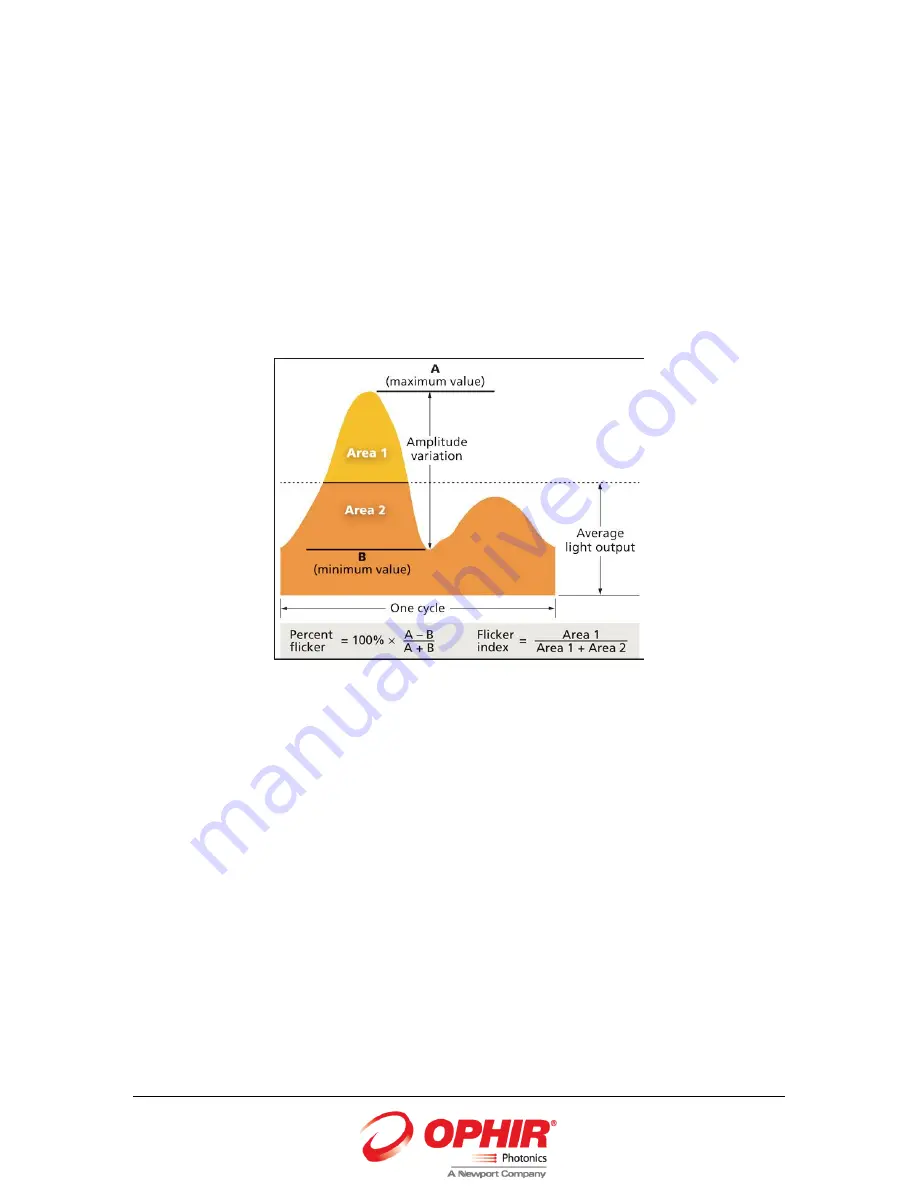
Percent Flicker and flicker factor 

FluxGage has a fast photodiode detector which samples at 3000Hz. 

The percent flicker and flicker factor calculations are explained in the following figure 


Summary of Contents for FluxGage

Page 1: ...FluxGage LED Luminaire Measurement System User Manual FluxGage FluxGage...

Page 2: ...s 19 7 3 Optimization Factors 20 7 4 Synchronized Measurement 21 7 5 Indicators 21 7 6 Measured Parameters 21 7 7 Flicker Screen 23 7 8 CRI screen 24 7 9 CIE 1931 Chromaticity 25 7 10 Spectrum Screen...

Page 3: ...User Manual 3 1 Acronyms DUT Device Under Test CCT Correlated Color Temperature CRI Color Rendering Index PPF Photosynthetic Photon Flux PAR Photosynthetically Active Radiation PAR Avogadro constant 6...

Page 4: ...early no light bounces back again This greatly reduces the effect of the DUT s size and shape on the measurement An integrated spectrometer is used to measure color parameters CCT CRI Duv and CIE 1931...

Page 5: ...Standards CE ROHS Interface USB Operation voltage 12v power adapter is supplied Accuracy Repeatability Total flux 3 Absolute calibration at Ophir Referenced to customers laboratory for a particular t...

Page 6: ...s CE ROHS Interface USB Operation voltage 12v power adapter is supplied Accuracy Repeatability Total flux 3 Absolute calibration at Ophir Referenced to customers laboratory for a particular type of lu...

Page 7: ...s CE ROHS Interface USB Operation voltage 12v power adapter is supplied Accuracy Repeatability Total flux 3 Absolute calibration at Ophir Referenced to customers laboratory for a particular type of lu...

Page 8: ...s CE ROHS Interface USB Operation voltage 12v power adapter is supplied Accuracy Repeatability Total flux 3 Absolute calibration at Ophir Referenced to customers laboratory for a particular type of lu...

Page 9: ...Electrical Installation 4 1 Unpacking Place the FluxGage box on a flat surface Open the box and remove the top piece of foam Remove two side pieces of foam Reach into the clearance left by the two pi...

Page 10: ...ly to the mains and to the DC input The power plug is secured by turning it half turn clockwise Connect the PC to the USB port The inner surfaces can be cleaned with a damp cloth or clean compressed a...

Page 11: ...FluxGage User Manual 11 5 PC and Software Installation Select 32bit or 64bit according to the operating system Install Double click on setup exe Install start...

Page 12: ...FluxGage User Manual 12 Click on Next...

Page 13: ...FluxGage User Manual 13 Click on Next...

Page 14: ...FluxGage User Manual 14 Install in progress...

Page 15: ...FluxGage User Manual 15 Click on Finish 5 1 Uninstall To uninstall go to Control Panel Programs Programs and Features Select FluxGage and Uninstall...

Page 16: ...the FluxGage and turn it on Press Autoset The FluxGage will automatically set the integration time of the spectrometer and other internal settings Step 2 Background Turn the DUT off Press Background...

Page 17: ...FluxGage User Manual 17 7 Operating the FluxGage SW...

Page 18: ...PDF report Exit Exit the SW Mode Flicker Detailed flicker screen CRI Detailed CRI Color Rendering Index screen CIE1931 Chromaticity coordinates Spectrum View and save spectrum in W nm PAR Detailed PAR...

Page 19: ...the actual measurement 7 2 3 Averages Adding averaging will improve the stability of the measurement If the integration time multiplied by the number of averages exceeds 500ms the photovoltaics and ph...

Page 20: ...l flux measurement The performance of the FluxGage system was optically modeled for various luminaire sizes and illumination beam angles and optimization factors adjust the total flux measurement acco...

Page 21: ...gh or too low for the current settings and Autoset and Background should be repeated Flux level exceed 40 000 lumen 7 5 3 Temperature The FluxGage has an internal temperature sensor and 4 fans which t...

Page 22: ...UV color space 7 6 5 Chromaticity Chromaticity coordinates in the CIE 1931 color space 7 6 6 Percent Flicker and flicker factor FluxGage has a fast photodiode detector which samples at 3000Hz The perc...

Page 23: ...calculated from the photodiode data after filtering at the bandwidth specified by the user This is useful to evaluate compliance with certain flicker standards Flicker Flicker percent after filtering...

Page 24: ...FluxGage User Manual 24 7 8 CRI screen The CRI screen shows the individual CRI values R1 R15 and the average value CRI...

Page 25: ...FluxGage User Manual 25 7 9 CIE 1931 Chromaticity The CIE 1931 chromaticity window shows the chromaticity coordinates...

Page 26: ...FluxGage User Manual 26 7 10 Spectrum Screen The spectrum is displayed from 400nm to 800mn in W nm units The spectrum can be saved to a text file by clicking over the disk icon...

Page 27: ...27 7 11 PAR screen PAR is measured in mol s also called PPF units One mol s is defined as Avogadro s number of photons per second There are 3 user defined wavelength ranges and the PAR is measured an...

Page 28: ...data over a time period Reference Enter user reference data Model Enter tested light source model or other reference information Save directory Select directory for log file Time Record Select durati...

Page 29: ...FluxGage User Manual 29 Stop Stop logging Play resume Start or resume logging Pause Pause logging Open last log Open the recent log file in the selected folder...

Page 30: ...and save to reach this screen This screen is used to save the current measurement data to a tab delimited test file Reference Enter user reference data Model Enter tested light source model or other r...

Page 31: ...er Manual 31 7 14 Save to Excel Enter operator and product details for reference Click on the folder icon in the file name part of the screen Select an existing file or type a new file name Click on a...

Page 32: ...on on the operator model part number serial number Enter the luminaire ratings flux power voltage beam angle CCT Enter actual electrical parameters as measured power power factor Click on the disk ico...

Page 33: ...FluxGage User Manual 33...

Page 34: ...FluxGage User Manual 34...

Page 35: ...FluxGage User Manual 35...

Page 36: ...cause its IR radiation is detected by the solar panels but not by the spectrometer Follow these steps To calibrate the FluxGage click Calibration on the top banner Position the calibration source over...

Page 37: ...brate the FluxGage click Calibration on the top banner Position the calibration source over the FluxGage In the setting area enter the total luminous flux of the calibration source in the luminous flu...

Page 38: ...ete At the top of the screen the measured flux of the calibration source will appear It should match the value entered in the settings area Click on the top right corner to exit the window 8 4 Back up...

Reviews: