background image

Graphical Displays 


StarBright User Manual 


57 

3.


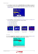
Set  the 

Levels

  as  needed.  Select  each 

LOW,  MED,  HIGH

,  press  the 

Enter

  key  to  display  the 

relevant window in which you can change the percentage using the up/down Navigation keys. 
(The default levels are LOW=30%, MED=60%, High=90%.) For example, see the “Low” window 
in 

Figure 

9-8 below

: 


Figure 

9-8  Changing Low to 40% 

4.


Press  the 

Enter

  key  to save  the setting. 

Figure 

9-9,  Figure 

9-10,  Figure 

9-11

, and

  Figure 

9-12 

below 

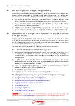
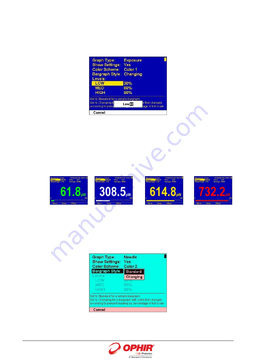
show sample colored bargraph power readings, indicating:  


Green

less than 30% full scale 


White

: 30% to 60% full scale 


Yellow

: 60% to 90% full scale 


Red

: greater than 90% full scale 


Figure 

9-9  Bargraph 

Green < 30% Full Scale 


Figure 

9-10  Bargraph 

White 30% to 60% 


Figure 

9-11  Bargraph  

Yellow 60% to 90% 


Figure 

9-12  Bargraph 

Red > 90% 

Standard 

You can set the 

Bargraph Style

 to 

Standard

 for a simple bargraph in full scale, using the 

procedure


above. Select 

Standard

 instead of 

Changing

. (The 

Levels

 options are disabled.) 


Figure 

9-13  Bargraph Style Set to Standard  

Summary of Contents for StarBright

Page 1: ...StarBright StarBright StarBright Laser Power Energy Meter User Manual...

Page 2: ...StarBright Youtube t...

Page 3: ...4 Energy Average Power or Exposure Measurement 10 2 5 Graphical Displays 10 2 6 Math Functions 12 2 7 Logging Data to a File for Upload to PC 12 3 Using the StarBright Display Unit 13 3 1 General Des...

Page 4: ...electric Sensors Method of Operation 44 8 2 Photodiode Energy Sensors Method of Operation 44 8 3 Measuring Pulses of High Energy Density 45 8 4 Operation of StarBright with Pyroelectric and Photodiode...

Page 5: ...verage 75 10 4 Fixed Offset 75 10 5 Scale Factor 76 10 6 Normalize 77 10 7 Density 78 10 8 Function Limitations 79 11 Logging Data to a File for Upload to PC 80 11 1 Launching the Log Setup 80 11 2 Se...

Page 6: ...Method of Factory Calibration 106 14 3 2 Accuracy of Calibration 106 14 3 3 Updating Photodiode Sensor Calibration Factors 107 14 4 Calibration of Pyroelectric Sensors 108 14 4 1 Absorber Types Used...

Page 7: ...een and store the new calibration in the sensor You can also zero the StarBright at the touch of a button StarBright is capable of logging data onto a USB Flash Drive Disk On Key as well as real time...

Page 8: ...will be performed by briefly pressing the On Off switch after the StarBright has been switched on 3 To switch the StarBright off press the On Off switch and hold it for 2 seconds until the display bla...

Page 9: ...ted in Sensor Specifications Otherwise there is a risk of damaging the absorber 2 2 2 Using StarBright to Measure Laser Power 1 Set Measuring to Power 2 Set Range to AUTO or one of the manual ranges T...

Page 10: ...t Wavelength to the appropriate laser wavelength If the wavelength you want is not among the wavelengths listed select one and press Modify Using the up down Navigation keys to change each number and...

Page 11: ...o the correct laser wavelength If this sensor is a metallic type and if the wavelength you want is not among the wavelengths listed select one and press Modify Using the up down keys to change each nu...

Page 12: ...r s frequency To measure exposure 1 Set Measuring to Exposure 2 Set measurement parameters as described above 3 Set Stop Mode to Manual Timeout period or Pulse count 4 Accumulated energy exposure will...

Page 13: ...verage Standard Deviation Total Readings and Number Overrange 4 To subtract the background and set the current reading to zero press the Offset button Press Offset again to cancel 5 Press Reset to cle...

Page 14: ...working with beam splitters To normalize against a reference measurement 1 Press Menu and enter Functions Go to Normalize 2 Set to reference value by which to normalize all subsequent measurements To...

Page 15: ...nhances measurement readouts in ways that simple monochrome displays cannot The StarBright can graph power or energy versus time It displays power measurements in both digital and analog form simultan...

Page 16: ...pped with LCD Display screen Soft keys under the display screen The functions of the keys change as indicated by the legend above each key The Menu key enables you to access Sensor Display Functions I...

Page 17: ...s section describes the StarBright hardware components and interfaces Topics include Sensor Input LCD Display and Backlight Soft Keys Navigation Keys On Off Switch Backlight Control Charger Input Anal...

Page 18: ...the StarBright screen have functions defined by the legend above each key The legend usually indicates what will happen when pressing the key For example if Zoom appears above a key pressing that key...

Page 19: ...Instrument Settings screen appears displaying the configurations saved from the previous session see Instrument Settings For example Figure 3 5 Instrument Settings Screen If a sensor is connected the...

Page 20: ...hours Pyroelectric and BeamTrack Low 16 hours Pyroelectric and BeamTrack Half 15 hours Pyroelectric and BeamTrack Full 13 hours Note Battery charge will be depleted faster if a USB Flash Drive Disk o...

Page 21: ...Outputs The StarBright is equipped for either RS232 or USB communications with PC The Unit is supplied with a standard cable for USB communications and a custom cable for RS232 see Figure 3 7 above Yo...

Page 22: ...libration date You can also re zero the instrument Click the links to view more details To configure the instrument settings 1 Disconnect the sensor The Instrument Settings screen is displayed Figure...

Page 23: ...ge Set desired instrument startup language Options include English Japanese Russian Chinese Line Frequency Set local line frequency to screen out electrical noise from the mains supply to prevent any...

Page 24: ...surement laser power energy meters products laser power meters starbright and copy it to your target directory 2 Run the upgrade executable and follow the on screen instructions Figure 3 9 StarBright...

Page 25: ...ent 5 Press Exit to return to the main screen For Thermopile Sensors only For best results with Thermopile sensors it may be necessary to do the procedure once with the sensor disconnected then afterw...

Page 26: ...e main screen use the Down Navigation key to select Language and press the Enter key 2 Set to English Japanese Russian or Chinese 3 Press the Enter key to save the new setting Note If you mistakenly s...

Page 27: ...ffset key to remove it from the measurement Figure 3 11 Bargraph Needle Simulates an analog display similar to the style of an analog voltmeter or a car s speedometer Available when measuring power or...

Page 28: ...ors Sum of the total energy of a series of pulses over a given time period or number of pulses This gives the total energy exposure over that time period For example if the laser is pulsing at 30 time...

Page 29: ...color schemes For example the following sensor displays Figure 3 19 Thermopile Sensor Monochrome Figure 3 20 Photodiode Sensor Monochrome Figure 3 21 Pyroelectric Sensor Full Color Full Color To set...

Page 30: ...ective glasses that filter out colors in the visible part of the wavelength spectrum These color schemes apply to all of the screens All color enhanced features of the StarBright will not be functiona...

Page 31: ...ser measurements at the top including Measuring on upper left for setting the measurement mode for example Power Energy and so on The configuration settings are sensor specific and saved in the sensor...

Page 32: ...t other instrument settings do you need to configure Do you use the analog output and if so is it configured correctly for your needs How would you like to display the measurement data as a bargraph a...

Page 33: ...ses the display unit to respond faster than the thermal rise time of the detector disc thus reducing the response time of the StarBright Energy of a single pulse is measured on the StarBright by digit...

Page 34: ...he settings Note The StarBright automatically saves the current settings for the next power up Warning Do not exceed maximum sensor limits for power energy power density and energy density as listed i...

Page 35: ...graph showing laser power measurement statistics Figure 5 2 Thermopile Power Statistics Display Note The soft key legend options such as Zoom Offset Persist Reset vary per Graph Type 5 3 Measuring Las...

Page 36: ...ment may trigger spuriously on the noise or background radiation It would then fail to measure the intended pulse Since there is always some degree of noise or background radiation the instrument is d...

Page 37: ...Average Energy per pulse Total Energy Number of Pulses In both of the above methods the pulse repetition rate must exceed 3Hz Higher rates will generally give improved accuracy but care should be take...

Page 38: ...he position of the center of the beam to a high degree of accuracy In addition to the 4 quadrants there is a special patented beam size detector After processing outputs from these various detectors t...

Page 39: ...r varies widely In autorange you do not have to change scales When the reading of the meter or bar is more than 100 of full scale the range goes to the next higher one The ranges are arranged in facto...

Page 40: ...beam 4 Press Offset to subtract the background noise from the measurement and reset the value to zero Figure 6 2 Position Display with BeamTrack Sensor 6 3 Tracking Stability Laser Beam Position Over...

Page 41: ...the desired signal The subtraction is not perfect but usually 98 of the background signal is eliminated so the detector can usually be used in ordinary laboratory lighting conditions The StarBright d...

Page 42: ...633nm 300mW 1W 3W 300mW 1W 1 4 m 0 8mW 150mW 670nm 200mW 500mW 2W 300mW 2W 1 5 m 0 8mW 150mW 800nm 100mW 300mW 1 2W 150mW 3W 1 6 m 0 8mW 150mW 900mm 150mW 300mW 1 2W 150mW 3W 1 8 m N A N A 1060nm 250m...

Page 43: ...todiode sensors have a different sensitivity at different wavelengths Moreover the filters used in the sensor have a different transmission at different wavelengths In order to compensate each sensor...

Page 44: ...s the Enter key Figure 7 1 Modifying the Wavelength Photodiode Sensor 4 Set the removable Filter setting to IN to measure higher power or to OUT for more accuracy and a wider wavelength range as physi...

Page 45: ...icowatt measurements using the PD300 IRG or PD300 UV there will be a rather large zero offset coming from the detector as well as a considerable noise fluctuation Nevertheless you can measure these lo...

Page 46: ...detector sensor has sophisticated circuitry unique to Ophir patented that determines the baseline before the pulse is received measures the voltage after a pre determined interval amplifies it and hol...

Page 47: ...setup used the next time the system is powered up These settings can all be easily changed as described in the following procedures To use StarBright with Pyroelectric and Photodiode energy sensors 1...

Page 48: ...the sensor is in a quiet environment and not subject to pulsed radiation 2 Press Menu and select Instrument 3 Press Zero and Start Wait until Zeroing completed successfully appears Figure 8 1 Pyroele...

Page 49: ...gth setting for all pulse lengths In that case N A appears Warning Incorrect readings will result if pulse length is not set up correctly 4 Set Diffuser to IN or OUT as physically set on the sensor re...

Page 50: ...t rates up to 10Hz Note High sensitivity Pyroelectric sensors PE 9 PE 10 are very sensitive to vibration and therefore might read a false trigger when operating in an acoustically non stable environme...

Page 51: ...requency of the pulses have been measured by StarBright Note StarBright use when measuring power is the same as when measuring energy and has been described in full in section Operation of StarBright...

Page 52: ...Stop Mode to Manual Timeout period or Pulse count Accumulated laser energy exposure will be displayed on the screen as well as elapsed time and number of pulses measured 4 To stop exposure measurement...

Page 53: ...a screen with limits You can choose to show or hide measurement parameters and you can customize the color scheme and bargraph style This section describes the graphical displays available for present...

Page 54: ...s Large numeric display with statistics Pass Fail Tests for measurements outside the user defined range of acceptable readings Exposure Sum of the total energy of a series of measurements For sensors...

Page 55: ...he middle of the screen Bargraph displayed close to the bottom Soft key legends at the bottom of the screen To present measurements on a graduated scale bargraph 1 In Power or Energy mode press Menu a...

Page 56: ...y again to return to the unexpanded Bargraph display 9 2 3 Offset The Offset function can be used to subtract the background and set the current reading to zero For Thermopile and Photodiode Sensors M...

Page 57: ...ulse is actually 3 Joules 2 Joules will be displayed on the screen thereby indicating the difference between the two laser pulses 9 2 4 Measuring Loss Using the dB Offset Function Since dBm is a logar...

Page 58: ...and 90 it will be displayed yellow and above 90 of full scale it will be displayed red These are the default cutoff values They are fully configurable thereby allowing you to use the colors of the bar...

Page 59: ...igure 9 9 Figure 9 10 Figure 9 11 and Figure 9 12 below show sample colored bargraph power readings indicating Green less than 30 full scale White 30 to 60 full scale Yellow 60 to 90 full scale Red gr...

Page 60: ...ow what the full range of measurements actually is including the maximum and minimum readings of the present set of measurements Figure 9 15 Pyroelectric Energy Needle Display The Needle graph display...

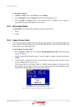
Page 61: ...urther details see Offset 5 Press Persist to keep older measurements on the screen and to display numerically the Min and Max values measured Press Persist again to cancel 9 3 1 Measuring Modes The Me...

Page 62: ...top of the screen Max and Min values on upper right above the Line graph Large numeric display above the Line graph Line graph displayed prominently in the middle of the screen The cursor at the tip...

Page 63: ...ay up the graph s height The scale of the graph will be 90 110 or 50 150 of the initial reading If the reading goes out of that range then the graph will be rescaled around the present reading 100 Gra...

Page 64: ...display Measurement statistics are also displayed Statistics displays are available when measuring power or energy Figure 9 21 Thermopile Power Statistics The Statistics display comprises the followi...

Page 65: ...useful for final inspection testing other aspects of Production Q A or field inspection of equipment If the measurement is out of range OVER or UNDER will be displayed on the screen If the Color Sche...

Page 66: ...the present range and the initial default Lower Limit is 0 until the first time both values are set to something else To set the Upper and Lower Limits 1 Press the Upper or Lower key The respective Mo...

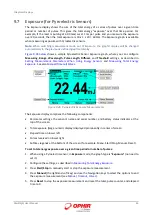
Page 67: ...rgy Sensors and Measuring Total Energy Exposure See also Manual Timeout Pulses Figure 9 26 Pyroelectric Exposure Measurements The Exposure display comprises the following components Parameter settings...

Page 68: ...Stops exposure measurement by the user pressing the Stop key Figure 9 27 Manual Option Selected Timeout Stops after the specified time has elapsed as shown on the key legend You can select 1 second 3...

Page 69: ...surement functionality This is available in the Track screen which shows the position of the laser beam as measured by the sensor If the beam is close enough to the center and the sensor is capable of...

Page 70: ...Track 9 9 Stability for BeamTrack Sensors The Stability display tracks the position of the laser beam over time This is useful for users that want to measure the pointing stability of their laser This...

Page 71: ...tion over time historical tracking for BeamTrack sensors only 1 When in Track mode press Menu and enter Display 2 Go to Graph Type and select Stability Return to the main display screen 3 Press the ra...

Page 72: ...and press the Enter key 4 Select Yes to show the settings or select No to hide them Figure 9 33 Show Sensor Settings Figure 9 34 Hide Sensor Settings 5 Press the Enter key to save the settings 9 10 2...

Page 73: ...Press the Menu button and use the Navigation keys to select Display and press the Enter key 3 Use the Navigation keys to select Color Scheme and press the Enter key 4 Select the relevant full color s...

Page 74: ...features of the StarBright will not be functional in any of the monochrome screens Follow the procedure above to set the color scheme and choose one of the following monochrome schemes Black White Bl...

Page 75: ...m that there is more to be seen A Right Arrow on the upper right indicates additional functions are available Pressing the Navigation key displays the Function and Pass Fail settings And subsequently...

Page 76: ...nts Top left of screen displays the power energy measurement without applying any of the functions Top right of screen displays the power energy measurement with applying all of the functions that hav...

Page 77: ...d you wish to average power over or set to NONE to disable This can also be set in the main measurement screen Figure 10 4 Setting the Average 10 4 Fixed Offset You can define a constant value to subt...

Page 78: ...cal beam splitter allows about 5 of the laser beam to get through In such a case the user would set the Scale Factor to 20 to get the actual output of the laser To apply a Scale Factor to measurements...

Page 79: ...u and enter Functions 2 Go to Normalize 3 Set to reference value by which to normalize all subsequent measurements The reference value can only be positive 4 Press Apply to set the present value as th...

Page 80: ...enter Functions 2 Go to Density Press the Enter key 3 Select the beam shape Disabled Rectangle Circle Selecting Rectangle enables the Height and Width parameters for modifying the spot height Selecti...

Page 81: ...isabled For BeamTrack sensors in Track mode the functions apply to the power measurement only For energy sensors in Exposure mode Average Normalize and Density are disabled If Normalize is active then...

Page 82: ...te the Log function you need to first connect an external storage device to the StarBright meter Once connected the Log Setup screen is displayed where you can configure the logging parameters and sta...

Page 83: ...lp in the lower area for the selected parameter Soft key legends at the bottom of the screen Start Start logging based on selected sensor and log parameters Files Enter the Log Files screen Exit Exit...

Page 84: ...Manual Mode Logging does not terminate at a predefined condition Rather it continues until the user presses the Stop key To set the Stop Mode to Manual 1 In the Log Setup screen set the Stop Mode to M...

Page 85: ...y Options Options include Sample Logs only the last reading that was measured Average Stores the average of all of readings that have been measured since the previous data has been added to the log 11...

Page 86: ...e before a new measurement is added to the log file The default interval is 0000 00 00 i e log each reading Figure 11 8 Setting the Interval Store By Determines the quality of the data that is stored...

Page 87: ...Setup screen displays the following parameters Figure 11 9 After Measurement Stop Mode 2 Go to each parameter and set the relevant options as required Log Size Number of readings that you want to sto...

Page 88: ...screen displays the graph type that was previously selected in the Display menu and the following additional parameters at the top of the screen Elapsed Time that has elapsed since starting the presen...

Page 89: ...be inactive and will be as it was when the log completed Figure 11 13 Active Logging Screen 5 When Start is pressed the logging counters will be reset the display will be cleared and activated The Sto...

Page 90: ...own At the bottom of the screen will be displayed general information of the presently highlighted file This includes the date and time of the log file hh mm ss duration number of logged readings numb...

Page 91: ...p down keys to scroll up down one page Use the right left keys to jump to the first last page 5 Press Exit to exit the Log Setup screen How the Various Types of Average Affect Logged Data Average that...

Page 92: ...for review at your workstation To view the log file on your computer 1 Remove the Disk on Key from StarBright and attach it to your PC 2 Start the StarLab application and select the Logging Menu 3 Se...

Page 93: ...as the standard PD300 which eliminates over 95 of background light and allows measurement in normal room light Differences between BC20 and Standard Thermopile Sensors Although BC20 sensors are Photo...

Page 94: ...e operation is the same as for other PD300 type heads Figure 12 2 PD300 CIE Screen Layout 12 3 PD300 BB The PD300 BB is a Photodiode based sensor with a flat spectral response Differences between PD30...

Page 95: ...ode can be set to Irradiance or Dosage Units The standard PD300 measures power and displays results in Watts W The PD300RM measures irradiance and shows results in Watts per area W cm or dosage as Jou...

Page 96: ...ollowing steps Enter Irradiance mode and go to the second set of soft keys by pressing the Right Arrow key Block the laser light source under measurement and press the Offset key This will activate th...

Page 97: ...the above basic analog circuit the StarBright contains a second fast analog input This supports certain Ophir sensors that read energy pulses at higher rates than can be supported by the basic analog...

Page 98: ...are protected by EMI protection component on all signals that pass in and out of the box In addition EMI protection is added internally to prevent disturbances to the normal functioning of the instrum...

Page 99: ...ation parameters In addition to NIST traceable factory calibration Ophir sensors can be field calibrated by the user Note Modifying calibration factors will affect the sensor s performance and should...

Page 100: ...hir Laser Absorbers Two types of absorber surfaces are used in Ophir Thermopile measuring sensors 14 2 2 Surface Absorbers BB Broadband Absorber On standard high power density broadband Ophir power mo...

Page 101: ...of choice for many applications Figure 14 1 Absorption vs Wavelength of Various Thermopile Sensor Absorbers Ophir power energy meters with the Broadband P or PF type absorbers are individually calibra...

Page 102: ...rs Method of Calibration The absorption of the various Ophir Thermopile absorbers can vary from disc to disc Therefore all Ophir absorbers are individually calibrated against NIST traceable standards...

Page 103: ...e of the screen and Updated factor and its effect on the reading on the right The Updated box on the right is highlighted indicating it is modifiable For more details see Sensitivity Power with Laser...

Page 104: ...ion Factor in Main Screen Response Available for all Thermopile sensors Optimize Thermopile response time of the sensor Use to attain accurate readings as quickly as possible and to minimize overshoot...

Page 105: ...if there is any The following procedure guides you through the specific steps To set calibration per Response factor 1 In the Select Calibration Factor screen select Response and press Continue The m...

Page 106: ...fter the scaling is completed the screen displays Block laser until power is close to O Figure 14 16 Scaling Completed 3 Press Next Figure 14 17 Response Calibration Factor 4 Adjust the Response Facto...

Page 107: ...se Factor values Figure 14 20 Scaled Present and Response Factor Values Updated Then the screen displays the final Response Factor value Figure 14 21 Final Response Calibration Factor Value The graph...

Page 108: ...ivity curve of the detector as well as the spectral transmission curve of the filters is fed into the sensor EEROM and this information is used to set the gain to the proper value at wavelengths other...

Page 109: ...ctor for one setting has no effect on power readings in the other settings To update Photodiode sensor calibration factors 1 Press Menu and select Calibration The screen displays the following general...

Page 110: ...Exit to return to the Menu screen 14 4 Calibration of Pyroelectric Sensors 14 4 1 Absorber Types Used in Ophir Pyroelectric Measuring Sensors The main absorber surface types used in Ophir Pyroelectri...

Page 111: ...d by the laser frequency The metallic PE25 and PE50 sensors are also calibrated with an excimer laser at 248nm to correct the rather large absorption variations in that spectral region with those sens...

Page 112: ...4 4 Updating Pyroelectric Sensor Calibration Factors Calibration of Pyroelectric sensors is only done when they are measuring energy As such if the sensor was in power or exposure mode entering the ca...

Page 113: ...or all laser settings There is an overall calibration factor for each pulse width option available in the sensor For sensors with a removable diffuser there are two sets of factors one set for each di...

Page 114: ...more than 10 the reading on the display is blanked Low Battery When the battery is almost discharged the Battery icon will have only 1 segment left This means the battery is empty At this stage the S...

Page 115: ...the sensor connector should be about 1 8k If the sensor is defective there will be an open or short circuit Instrument responds while sensor is cold but suddenly fails as it heats up Have the sensor d...

Page 116: ...a charge a replacement can be ordered from your agent Ophir part number 7E14008 The new battery is installed as follows 1 Ensure the StarBright is switched OFF Turn the StarBright meter upside down a...

Page 117: ...Pyroelectric Sensors Input Range 0 6V full scale A to D Sampling rate 5000 Hz A to D resolution 12 bits no sign 0 025 resolution Electrical accuracy 0 25 new 0 5 after 1 year Electrical input noise 2m...

Page 118: ...mopile Photodiode 17 Pyroelectric 15 With high backlight Thermopile Photodiode 15 Pyroelectric 13 Note Battery charge will be depleted faster if a USB Flash Drive is left plugged in the StarBright met...

Page 119: ...0THz 50W cm P 3A FS 3W 1000W cm FS 10A 10W 28KW cm BB 12A 12W 25KW cm BB 12A P 12W 50W cm P 20C SH 4 20 W 23KW cm BB 30A BB 18 30W 20KW cm BB 30A P 17 30W 50W cm P L30A 10MM 30W 20KW cm BB 50A PF DIF...

Page 120: ...000W LP1 50 5000W 2KW cm BB LP1 10K W BB 45 10 000W 10KW cm BB 30K W BB 74 30 000W 10KW cm BB 100K W 100 000W 120K W 120 000W Comet 1K Comet 10K 1KW 10KW 4KW cm 1KW cm BB BDFL500A BB 50 500W 7KW cm BB...

Page 121: ...otodiode P P type volume absorber for short pulse lasers PF Volume absorber for short pulses and high average powers HE HE1 Volume absorber for high energy pulses EX Excimer type volume absorber PE Py...

Page 122: ...rbers Single Pulse Absorber Type Max Energy Density J cm Pulse Length 10ns 1 s 300 s P 10 10 10 HE 3 5 15 BB 0 3 0 5 3 LP1 0 09 0 5 10 EX 0 8 0 6 7 PF 1 5 1 5 5 N 0 3 1 15 PE Metallic 0 1 0 5 4 PE BB...

Page 123: ...rBright User Manual 121 Figure 15 2 Pulsed Laser Damage Threshold for Pyroelectric Sensors StarBright User Manual Ophir P N 1J06062 25 Nov 2015 Rev 1 18 1 For the latest version please visit our websi...

Reviews: