background image

Biopel line – CS-65 GSM modul user manual 


2  MENU DESCRIPTION 


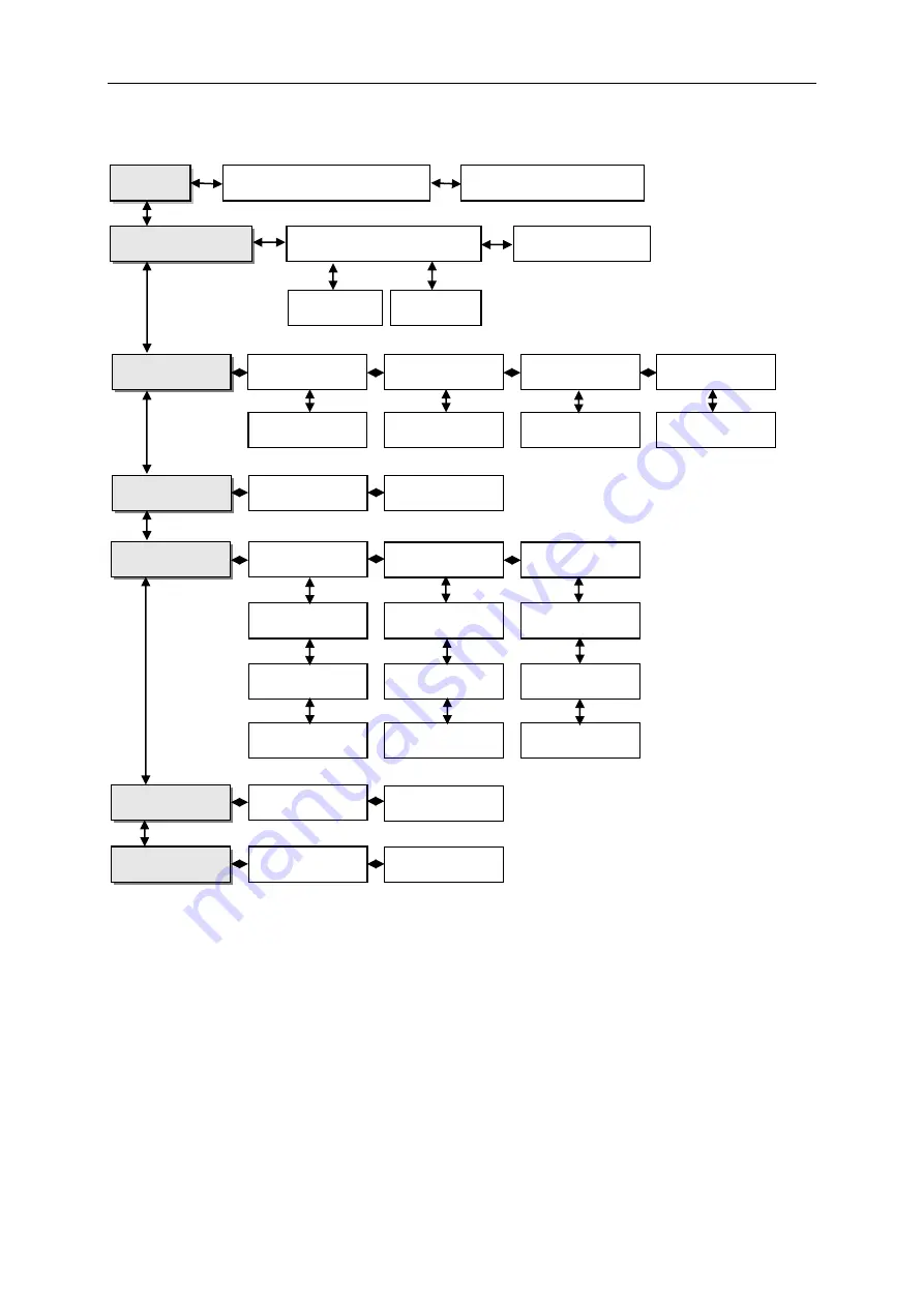
You  can  find  detailed  menu  description  below,  when  you  go  through  this  user  manual.  Read  all 
instruction below to successfully activate GSM modul and use it without any problems.  

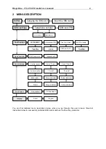
MENU 

Canging the SIM card 

Insert the SIM card 

GSM settings 

Telephone number 

SIM card PIN 

1<<<<<

2<<<<<


Notification 

Activated 

Authorisation PIN


Time of next alert 

Notif. No supply 

Yes/No 

(1234)


1/300 min, 0-off 

Yes/No 

Operation mode 

With the conroller


Independently


Sensor settings 

Config. imputs


Conn. T1 sett.


Conn. T2 sett.


Active, Inactive


Alarm when…


Name


T1 on/off


Temp. maximum


Temp. minimum


T2 on/off


Temp. maximum


Temp. minimum


Conf. outputs 

On by default


Off by default


Language 

Polish


English


Summary of Contents for Biopel Ash Removal 10/15

Page 1: ...using this device properly Cleaning itself is easier because of external container which is easy to clean and attach back on the boiler There are 3 types of as removal devices considering Biopel boile...

Page 2: ...INDEX 1 PACKAGING 3 2 ASSEMBLY 4 3 WARRANTY CONDITIONS 7...

Page 3: ...of ash removal you can find parts included in the list below Ash container with top lid Ash door Second ash door lock first is on the boiler body assembled in the factory Screw with motor and attache...

Page 4: ...er ash doors Remove pin and rod which holds doors on the place Remove standard ash tray from the boiler as well Remove cover on the back side of the boiler along with flap which is secured by 2 screws...

Page 5: ...connect metal holder on the back side of the boiler body by using 2 screws Insert 230V socket into the back cover and attach this cover back on the boiler by screws Connect second ash door lock on th...

Page 6: ...ger is properly positioned inside the ash container Connect power supply cable to the socket on the back side of the boiler and to the connection boart to the output called Dashing Activate ash remova...

Page 7: ...expense provided that the boiler it is in normal condition according to the Instruction manual is connected to a chimney according to CSN 73 4201 1989 is not damaged mechanically no unauthorized inte...

Page 8: ...o Za ovsk 750 757 01 Vala sk Mezi Bank details Komer n banka a s account no 1608851 0100 Reg no 47674105 VAT no CZ 47674105 Phone Sales Dept 571 675 589 Secretariat 571 611 250 Production 571 675 405...

Page 9: ...essor cleaning is additional device which can be implemented into the Biopel burners and boilers You can use it for cleaning of burner s grate as well as for exchanger cleaning This manual is for comp...

Page 10: ...INDEX 1 COMPRESSOR BURNER CLEANING 10 200KW 3 1 1 PACKAGING 3 1 2 ASSEMBLY 3 2 SETUP 6 3 WARRANTY CONDITIONS 7...

Page 11: ...duction x Fitting reduction 3 8 x Fitting socket Fitting nipple reduced x 4pcs angled connector straight Angled connector with two outlets Angled connector with four outlets 4pcs circlip 1 2 Assembly...

Page 12: ...noid valve with fitting reduction x Connect fitting reduction x with fitting socket Connect angled connector with two or four outlets Insert all burner pipes into the burner Extended end of the pipe h...

Page 13: ...nnctors straight Connect other side of PVC hoses small to the angled connector with two outlets for small burners Connect cable from magnetic velve into the connection board Connect 230V cable of the...

Page 14: ...ice menu Auger Work Operation control set 10s If there is no flame after compressor cleaning photosensor doesn t detect the light After 10s control unit goes to ignition again automaticly Setup in com...

Page 15: ...s at our expense provided that the boiler it is in normal condition according to the Instruction manual is connected to a chimney according to CSN 73 4201 1989 is not damaged mechanically no unauthori...

Page 16: ...s r o Za ovsk 750 757 01 Vala sk Mezi Bank details Komer n banka a s account no 1608851 0100 Reg no 47674105 VAT no CZ 47674105 Phone Sales Dept 571 675 589 Secretariat 571 611 250 Production 571 675...

Page 17: ...ntrols by your home computer states of the installation of the boiler and work of each unit is displayed in animated form on the screen Besides there is a possibility of displaying the temperature sen...

Page 18: ...ONNECTION 3 1 1 MODUL CONNECTION VIA LAN 3 1 2 MODUL CONNECTION VIA EXTERNAL PAGE 3 1 3 SETTING SECURITY PROTECTION 4 1 4 MANUAL ADJUSTMENT MODULE 4 1 4 1 Downloading data 4 1 4 2 Configuring control...

Page 19: ...assword field blank and click OK After these activities are already logged into the module via the local network 1 2 Modul connection via external page If we don t want to use only local network at ho...

Page 20: ...ters In this case we have to check the settings for your local network We will need the following parameters o IP Address o Mask IP o Gateway Address o DNS Address 1 4 1 Downloading data Click on the...

Page 21: ...1 200 If there is an information display Destination host unreachable then the address is free and can be used In the case when we get feedback we need to use different IP address MAC Address is set...

Page 22: ...vsk 750 757 01 Vala sk Mezi Bank details Komer n banka a s account no 1608851 0100 Reg no 47674105 VAT no CZ 47674105 Phone Sales Dept 571 675 589 Secretariat 571 611 250 Production 571 675 405 Sourci...

Page 23: ...nted on Biopel 10 40 This device moves with turbulators which are installed inside heat exchanger There are 2 sizes of exchanger cleaning On eis for Biopel 10 15 and second is for Biopel 20 30 Instala...

Page 24: ...INDEX 1 PACKAGE CONTENT 3 2 ASSEMBLY 4 3 WARRANTY CONDITIONS 6...

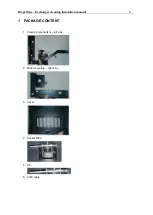
Page 25: ...Biopel line Exchanger cleaning instalation manual 3 1 PACKAGE CONTENT 1 Cleaning mechanism left side 2 Motor mounting right side 3 Cover 4 Socket 230V 5 Pin 6 230V cable...

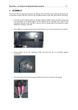
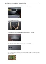
Page 26: ...installed Motor and all mounting parts are assembled in the OPOP factory to be mounted on the left side If you want to use exchanger cleaning on the right side than you have to disassemble it and asse...

Page 27: ...icture below Full assemble shuld look like this Place cover on the side of the boiler and connect 230V cable in to the socket Pass the 230V cable through the holes on the side of compact tank Connect...

Page 28: ...as soon as at our expense provided that the boiler it is in normal condition according to the Instruction manual is connected to a chimney according to CSN 73 4201 1989 is not damaged mechanically no...

Page 29: ...s r o Za ovsk 750 757 01 Vala sk Mezi Bank details Komer n banka a s account no 1608851 0100 Reg no 47674105 VAT no CZ 47674105 Phone Sales Dept 571 675 589 Secretariat 571 611 250 Production 571 675...

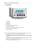
Page 30: ...e of a cell phone User is notified with an sms message on every boiler control unit alarm Additionaly by sending an appropriate sms message at any time user receives a return message with the informat...

Page 31: ...CRIPTION 4 3 SIM CARD 5 4 COLLECTING DATA FROM THE CONTROLLER 6 5 DATA COLLECTION AND SETTINGS 7 5 1 PIN AUTHORISATION 7 5 2 ACTIVATION DEACTIVATION OF ALERT NOTICES 7 5 3 OPERATION MODE 8 6 TECHNICAL...

Page 32: ...ollowing safety principles must be observed 1 All installation works should be performed after disconnecting voltage 2 Before activating the modul it should be checked whether in the vicinity there is...

Page 33: ...card Insert the SIM card GSM settings Telephone number SIM card PIN 1 2 Notification Activated Authorisation PIN Time of next alert Notif No supply Yes No 1234 1 300 min 0 off Yes No Operation mode W...

Page 34: ...switch to standby mode waiting for the card to be changed wait for a message as above To insert the card unscrew four fixing screws and open the casing After inserting the sim card press any button t...

Page 35: ...The sms is sent to any authorised phone number After sending the authorisation pin to the module phone number data with controller working parameters will be sent back The quantity and type of sent da...

Page 36: ...ng to the module phone number a message in the format below Current pin authorisation space command 1234 off Namely 1234 off A message of this type will deactivate sending alert messages from the modu...

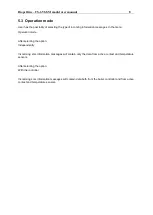
Page 37: ...menu Operation mode After selecting the option Independently Incomming sms information messages will contain only the data from active contact and temperature sensors After selecting the option With...

Page 38: ...ct inserting of the battery can cause damage to the battery or device Type 1044 Capacity 600MAh Voltage 3 7V Built in PCB protection against excessive discharging overcharging or short circuit Dimensi...

Page 39: ...soon as at our expense provided that the boiler it is in normal condition according to the Instruction manual is connected to a chimney according to CSN 73 4201 1989 is not damaged mechanically no un...

Page 40: ...o Za ovsk 750 757 01 Vala sk Mezi Bank details Komer n banka a s account no 1608851 0100 Reg no 47674105 VAT no CZ 47674105 Phone Sales Dept 571 675 589 Secretariat 571 611 250 Production 571 675 405...

Page 41: ...parental lock to protect against unwanted changes to settings By using the thermostat you will be able to comfortably control the temperature in your home central heating system and the temperature o...

Page 42: ...F CONTROLLER FUNCTIONS 6 1 2 1 Time 6 1 2 2 Safety devices 8 1 2 3 Screen 8 1 2 4 Weekly control 9 1 2 5 Furnance control 10 1 2 6 Language selection 13 1 2 7 About the program 13 1 2 8 Settings 13 2...

Page 43: ...above screen view is the default view for the RT10 controller under its factory settings You can change it to Panels screen The view can be changed with the arrow buttons in the right or left paramet...

Page 44: ...ters panels View showing the current and set temperature inside the room when you press this panel you can change the room set temperature View showing the current and set temperatures of the furnace...

Page 45: ...uch information from the furnace controller Graph showing the current temperatures of the furnace water heater or inside the room It provides graphic presentation of temperature changes over time View...

Page 46: ...in the instructions manual of the furnace controller 1 1 Thermostat menu During normal operation of the thermostat the graphic display shows the main page After pressing the menu button the user can...

Page 47: ...clock You can set the alarm clock to go off only on selected days of the week active on selected days or set it to go off once Use the up and down arrow keys to set your alarm time If the alarm is to...

Page 48: ...hen you press the Auto lock icon a panel will be shown that can be used to enable or disable the lock To set your PIN code which you will need to operate the thermostat when the lock is enabled press...

Page 49: ...ll be shown for adjusting the night time appearance of the screen with the following options available As at daytime Clock and Off Screensaver as a clock The rest of the screen menu can be used to set...

Page 50: ...fter selecting the day of the week a panel will be displayed for setting temperature deviations at selected time intervals To make these settings easier you can copy a set deviation value for the next...

Page 51: ...to easily change the pumps operations mode in furnace controller with the following options available Home heating furnace priority Pumps in parallel and Summer mode A detailed description of the ope...

Page 52: ...inside the room and as per the daily operation schedule of the furnace The existing temperature inside the room will be prioritized under this mode if the room temperature drops below a temperature t...

Page 53: ...ttings 1 2 6 Language selection Press the Language selection icon in the main menu to access the user language selection panel 1 2 7 About the program Press this icon to display the logo of the furnac...

Page 54: ...imal temperature fluctuations between 0 2 and 4 C with an accuracy of 0 1 C For example when your temperature set point is 23 C and the hysteresis value is set to 1 C the room thermostat will start to...

Page 55: ...ated the room thermostat will sound a beep and the display will show the same message as that on the furnace controller If the internal sensor suffers damage an alarm will be displayed saying Room tem...

Page 56: ...controller mounted on the CH furnace with a four wire communication cable and the room thermostat power supply unit The cable connections of both devices are shown in the diagram below Sequence of wir...

Page 57: ...oon as at our expense provided that the boiler it is in normal condition according to the Instruction manual is connected to a chimney according to CSN 73 4201 1989 is not damaged mechanically no unau...

Page 58: ...ovsk 750 757 01 Vala sk Mezi Bank details Komer n banka a s account no 1608851 0100 Reg no 47674105 VAT no CZ 47674105 Phone Sales Dept 571 675 589 Secretariat 571 611 250 Production 571 675 405 Sour...

Page 59: ...Biopel wirelles modul CS260 for RT10 Instalation manual You can use our room thermostat RT10 wirelessly with combination of CS260 modul Folow these simple steps to connect this modul correctly...

Page 60: ...of RJ45 ethernet cable connect this device into the RT10 romm regulator as well Connect ST260v1 in to the RJ45 socket which is located on the side of connection board Activate RT10 room regulator in...

Page 61: ...ded that the boiler it is in normal condition according to the Instruction manual is connected to a chimney according to CSN 73 4201 1989 is not damaged mechanically no unauthorized interference with...

Page 62: ...Vala sk Mezi Bank details Komer n banka a s account no 1608851 0100 Reg no 47674105 VAT no CZ 47674105 Phone Sales Dept 571 675 589 Secretariat 571 611 250 Production 571 675 405 Sourcing 571 675 114...

Reviews: