background image

Wiring

7

Wiring

For connecting the sensor cables, observe the following basic conditions:

• Bring the sensor cable to the cable entry from underneath.

• Form a loop with the sensor cable close to the cable entry.

• Do not lay sensor cables in ducts of current-carrying lines.

• Observe cable specifications (see technical data).

• To lay sensor cables underground without protection is prohibited.

For connecting the sensor to the converter, a sensor cable is provided.

Connection to the

sensor

Fig. 15:

Connector

Tool

F

not needed

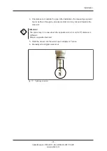
1. Loosen the connection cover of the sensor.

2. Loosen the plug cover on the sensor cable.

3. Insert the sensor cable until it audibly locks into place. Only then, the thread

grips.

4. Fasten the thread, until it locks into place. The connection is now fastened.

Fig. 16:

Connecting sensor cable

Notice!

Exact information about the connection of a sensor to a converter is given in the
instruction manual of the respective converter. There you can as well find the
corresponding wiring plans.

- 23 -

optek-Manual--1004-2011-02--AS56-US-2017-06-28

www.optek.com

Summary of Contents for AS56 Series

Page 1: ... 201 63409 0 E Mail info optek de Internet www optek com optek Danulat GmbH Emscherbruchallee 2 D 45356 Essen Instruction Manual optek sensors AS56 optek Manual 1004 2011 02 AS56 US 2017 06 28 PN 1004 2011 02 52 ...

Page 2: ...ion manual or products described herein This manual is protected by copyright However the user may produce copies and translations if required for correct operation of the products On request this manual is available in other languages as well as on a digital medium Acrobat Reader 7 0 Our products are being continuously improved Technical data is subject to change without notice Essen December 201...

Page 3: ...AS56 F AS56 N sensor 9 5 2 Accessories weld in port AS25 10 5 3 Accessories Varivent adapter port AS25 G60 12 5 4 Accessories Clamp adapter port AS25 G60 13 5 5 Accessories optek T pieces for pipe DIN 11850 14 5 6 Accessories optek T pieces for pipe OD 15 5 7 Accessories sealing flange AS25 16 5 8 Exploded view of AS56 F AS56 N sensor 17 6 Installation 18 6 1 General installation instructions 18 6...

Page 4: ... 9 4 2 Installation Kit 32 9 4 3 Gaskets not wetted 32 9 4 4 Gaskets wetted 32 9 4 5 Screw sets 32 9 4 6 Accessories cable sets stainless steel connector 33 9 4 7 Accessories process adapter 34 9 4 8 Accessories T piece for AS16 AS56 DIN 11850 35 9 4 9 Accessories T piece for AS16 AS56 OD BS 4825 1 35 10 EU declaration of conformity 36 11 Contacts 37 II optek Manual 1004 2011 02 AS56 US 2017 06 28...

Page 5: ...ow the instruction manual for every operation If the product is not used as described in this instruction manual your safety and the product function may be affected To keep up reliability of the product enhance its life cycle and avoid down times follow the instructions given in this manual Furthermore please follow the existing accident prevention and environmental protection instructions as wel...

Page 6: ... the symbol gives information on how to avoid bodily injuries If the possible cause of risk can be specified the corresponding pictogram precedes instructions Danger Electrical voltage This pictogram indicates danger due to electrical voltage Attention This pictogram indicates information on how to avoid material damage Notice This pictogram indicates instructional or general advice 2 optek Manual...

Page 7: ...ion and contact information can be found on our website www optek com 2 2 Disposal Special legal regulations apply to the return and disposal of industrial waste equipment However manufacturer and user can contractually agree on which party is to fulfill these legal obligations Observe current national disposal regulations For disposing of packaging material please separate materials paper cardboa...

Page 8: ...uildings regarding the sensor are prohibited The only exception are rebuildings into one of the variants listed in the chapter Validity of the instruction manual Changes to and interference with the converter program are prohibited as well Burying sensor cables underground without protection is prohibited The manufacturer is not liable for damage resulting from use contrary to the intended use Fol...

Page 9: ...3 1 5 Fig 2 Schematic AS16 AS56 1 Optical path length OPL 2 Sapphire window 3 Lamp 4 Optics module with filter 5 Detector The process medium is penetrated by a precisely focused constant light beam A hermetically sealed silicon photodiode measures intensity of incoming and optically filtered light and supplies the converter with it in form of photocurrent Attenuation of light intensity as a result...

Page 10: ...measurement and is defined for each measurement type with the help of optical filters The third factor of influence in the Lambert Beer Law is the path length of light passing through the process medium Equally proportional the path length too is an important aspect with regard to specification of a photometer The distance to be covered by light is defined through the optical path length OPL that ...

Page 11: ...ive measuring range specific to application Type of protection all optical parts have an IP rating of IP65 or higher Process adaption Material wetted parts stainless steel 1 4435 SS 316L surface electro polished Ra 0 8 μm housing stainless steel 1 4571 SS 316 Ti Port connection thread G1 1 4 in ISO 228 1 for port AS25 similar Ingold port diameter 25 mm D 25 H7 O ring groove for 30 mm and for 60 mm...

Page 12: ...le material non metallic sheathed cable with finely stranded copper conductor according to IEC 228 CL 5 insulation PVC 40 C 70 C 40 F 158 F Plug connection SS plug protector Cable weights probe cable 1 5 kg 10 m Cable diameter approx 9 5 mm approx 11 mm with shrink hose Certificates ISO 9001 2015 PED CE HP0 Pressure and temperature ratings specified herein may be subject to limitations The appropr...

Page 13: ... Fig 3 Dimensions AS56 F AS56 N sensor 1 OPL optical path length measuring gap 2 Lower O ring groove with approx 60 mm port length 3 Upper O ring groove with approx 30 mm port length 4 Swivel nut G 1 1 4 ISO 228 1 short approx 19 mm 5 Orientation mark for measuring gap 6 Probe head with optics and lamp module 7 Airpurge connection 9 optek Manual 1004 2011 02 AS56 US 2017 06 28 www optek com ...

Page 14: ...t the site The port may as well be welded in at an angle smaller than 15 because it is provided with the corresponding cone The three weld in ports are available as accessories Ø27mm 1 06 Ø24 7mm 0 97 50mm 1 97 58 3mm 2 3 G1 A ISO 228 1 30 Ø42mm 1 65 15mm 0 59 70mm 2 76 1 2 3 69 6mm 2 74 58 3mm 2 3 15mm 0 59 50mm 1 97 G1 A ISO 228 1 Ø27mm 1 06 Ø25mm 0 98 H7 15 Ø27mm 1 06 G1 A ISO 228 1 Ø25mm 0 98 ...

Page 15: ...elding distortion at the weld in port has to be corrected Modify the interior drill hole of Ø 24 7 mm to obtain the nominal diameter Ø 25 H7 Ø 25 0 Ø 25 021 mm before installing the probe 11 optek Manual 1004 2011 02 AS56 US 2017 06 28 www optek com ...

Page 16: ...ged clamp TU no 701 075 nut M6 TU no 912 035 and gasket Ø 60x3 EPDM FDA TU no 930 144 are parts included in the Varivent inline housing scope of supply As standard the adapter is delivered without these parts The sensor is inserted into the pipeline to a different degree depending on the applied optical path length and the variant Tab 2 Varivent adapter port AS25 G60 OPL mm AS56 L 35 mm OPL insert...

Page 17: ...andard the adapter is delivered without hinged clamp and gasket The sensor is inserted into the pipeline to a different degree depending on the applied optical path length OPL Tab 3 Clamp adapter port AS25 G60 OPL mm AS56 L 35 mm OPL insertion depth max mm 5 40 10 45 50mm 1 97 52mm 2 05 58 33mm 2 3 6 33mm 0 25 Ø25mm 0 98 H7 Ø30mm 1 18 Ø63 9mm 2 52 Ø56 5mm 2 22 Ø27mm 1 06 G1 A ISO 228 1 15mm 0 59 F...

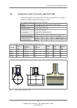
Page 18: ...ring groove for 30 mm 1 18 and for 60 mm 2 36 port length Admissible pressure PS 10 mbar 16 bar for TS 40 C 120 C 40 F 248 F Admissible pressure at increased temperature TS C 120 150 200 248 302 392 F PS bar 16 14 13 Tab 5 Dimensions for optek T pieces for pipelines according to DIN 11850 Line size Length L mm Pipe size diameter x S mm Inside diameter D mm Height H mm Depth H1 mm Maximum OPL mm DN...

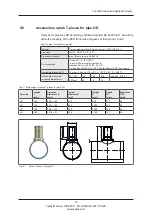
Page 19: ...mm 0 98 D 25 H7 O ring groove for 30 mm 1 18 and for 60 mm 2 36 port length Admissible pressure PS 10 mbar 20 bar for TS 40 C 120 C 40 F 248 F Admissible pressure at increased temperature TS C 120 150 200 248 302 392 F PS bar 20 18 16 Tab 7 Dimensions for optek T pieces for pipe OD Line size Length L mm Pipe size diameter x S mm Inside diameter D mm Height H mm Depth H1 mm Maximum OPL mm 2 0 150 5...

Page 20: ...0 weld in port and the 15 AS25 S60 weld in port and may as well be used for other and shorter weld in ports as the second groove for the O ring is located 30 mm 1 18 higher Both grooves are designed for O rings Ø 18 64 x 3 53 mm The swivel nut is designed for short threads G1 1 4 ISO 228 1 58 8mm 2 31 28 8mm 1 13 64mm 2 52 Ø25mm 0 98 19mm 0 75 57mm 2 24 Fig 9 Sealing flange AS25 16 optek Manual 10...

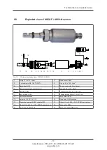
Page 21: ...p 7 Phoenix connector 3 pin detector 8 O ring 50 52 x 1 78 Viton 9 Housing OH02 10 2 collar screws M2 5 x 10 8 slot 11 lamp module AS56 12 2 threaded rods M4 x 87 DIN 976 A2 13 Connection detector 14 Lamp holder AS56 15 Swivel nut 35 G1 1 4 H19 16 Probe body AS56 polished 17 Measuring segment AS56 variable OPL 18 Option O ring 18 64 x 3 53 EPDM lower groove 19 Option O ring 18 64 x 3 53 EPDM upper...

Page 22: ... port is possible product may adhere to the windows 2 Beveled top installation is recommended no entrapped gas at top of port product drains off the windows easy insertion removal of sensor good cleanability 3 Horizontal installation is recommended no entrapped gas at top of port product drains off the windows easy insertion removal of sensor good cleanability 4 Beveled bottom installation is poss...

Page 23: ...r flow obstacles Make sure that no extraneous light sources are located near the sensor in order not to distort measuring results In rare cases seizing of threads may occur An appropriate lubricant has thus to be used Apply lubricant as a thin film to the male thread of the port Appropriate lubricants are given in the spare parts list Do not exceed 25 bar during any pressure test Only remove a sea...

Page 24: ...the O ring will later be inserted into the process medium Lower groove is correct for 60 mm 2 36 port length Upper groove is correct for 30 mm 1 18 port length The measuring segment is further inserted into the process medium Notice Install only one O ring This way you avoid creation of a hold up volume or entrapment of process medium at the sensor 3 Slide the O ring into the lower or upper groove...

Page 25: ... not point towards the pipe wall Attention The probe may in no case touch the opposite wall a 5 mm 0 20 distance is sufficient Observe opposite internals 5 Slide the sensor into the weld in port adapter or T piece 6 Manually screw tighten swivel nut Fig 13 Tightening swivel nut 21 optek Manual 1004 2011 02 AS56 US 2017 06 28 www optek com ...

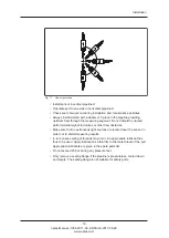
Page 26: ...ing 4 Place the air purge hose on the air purge connection 1 1 2 Fig 14 Airpurge connection on sensor example AS16 After connecting the sensor to the power supply and putting it into operation rinse it as described below 1 Loosen the cylinder nut 2 in Fig 14 turning it 2 3 turns anticlockwise 2 Rinse the optical housing by aerating it with dry oil and dust free air for approx 10 minutes at a maxim...

Page 27: ... sensor cable is provided Connection to the sensor Fig 15 Connector Tool F not needed 1 Loosen the connection cover of the sensor 2 Loosen the plug cover on the sensor cable 3 Insert the sensor cable until it audibly locks into place Only then the thread grips 4 Fasten the thread until it locks into place The connection is now fastened Fig 16 Connecting sensor cable Notice Exact information about ...

Page 28: ... the fault using the following table and the instructions given in the chapter Software in the instruction manual of the converter Should you have any difficulty clearing the fault feel free to contact our customer service See chapter 11 page 37 for our contact data 24 optek Manual 1004 2011 02 AS56 US 2017 06 28 www optek com ...

Page 29: ...r cable between sensor and converter defective Continuity test of detector cable Exchange detector cable for new one Sensor cable incorrectly connected to converter Check and revise connections Measuring range ex ceeded flashing at the converter Process conditions Amplify measuring range If the measuring range cannot be amplified reduce optical path length Wavelength dependent detector module redu...

Page 30: ...justing calibration of the receiving mA input Converter defective None of the above mentioned errors can be detected Send system converter and sensor to optek for checking purposes If necessary the sensor body can remain in the pipeline so that only the optical arms and the converter have to be sent 26 optek Manual 1004 2011 02 AS56 US 2017 06 28 www optek com ...

Page 31: ...f the sensor body can lead to leakages Lamp module exchange 1 2 years Operation of the lamp below its nominal voltage 4 8 V DC instead of 5 0 V DC enhances lamp life Strong vibrations high temperatures or frequent on and off switching of the system can have negative effects on the service life Statistical service life is 3 years Notice The used detector is not subjected to measurable aging when us...

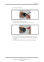
Page 32: ... cylinder nuts connecting the backplate to the housing and carefully remove the backplate Fig 17 Loosening cylinder nuts and removing backplate 4 Carefully loosen the lamp and detector connectors 5 Loosen both screws 1 in the figure below of the lamp module 1 1 Fig 18 Screws of lamp module 28 optek Manual 1004 2011 02 AS56 US 2017 06 28 www optek com ...

Page 33: ...module is fit in the sensor 1 1 Fig 20 Screws of lamp module 9 Verify that the O ring is provided on the backplate Replace it if necessary 10 Connect the 2 pin connector to the lamp module and the 3 pin connector to the detector 11 Place the backplate on the housing so that the drill holes correspond 29 optek Manual 1004 2011 02 AS56 US 2017 06 28 www optek com ...

Page 34: ...uts Fig 21 Placing backplate and fastening cylinder nuts 13 Re connect the sensor cable 14 Switch on the measuring system 15 Follow the instructions given in chapter 9 3 page 31 30 optek Manual 1004 2011 02 AS56 US 2017 06 28 www optek com ...

Page 35: ... 15 minutes until the converter has reached the working temperature 3 Check the system s zero point see instruction manual of the converter 4 Document your settings using the form see instruction manual of the converter 5 Check the measuring results with regard to plausibility 6 If the settings and measuring results are correct enable measuring 31 optek Manual 1004 2011 02 AS56 US 2017 06 28 www o...

Page 36: ...stallation Kit AS 1201 3401 0001 00 9 4 3 Gaskets not wetted Tab 12 Spare parts gaskets not wetted Description Name type Part number 4 x 0203 0001 02 O ring 4 00 x 1 00 Viton O ring 4 00 x 1 00 Viton 1203 0004 0001 02 4 x 0203 0021 02 O ring 50 52 x 1 78 Viton O ring 50 52 x 1 78 Viton 1203 0004 0021 02 9 4 4 Gaskets wetted Tab 13 Spare parts gaskets wetted Description Name type Part number 2 x 02...

Page 37: ...1331 0200 0010 00 15 m 49 ft Cable Set AS16 015 m SS 1 5 1331 0200 0015 00 20 m 66 ft Cable Set AS16 020 m SS 1 5 1331 0200 0020 00 25 m 82 ft Cable Set AS16 025 m SS 1 5 1331 0200 0025 00 30 m 98 ft Cable Set AS16 030 m SS 1 5 1331 0200 0030 00 35 m 115 ft Cable Set AS16 035 m SS 1 5 1331 0200 0035 00 40 m 131 ft Cable Set AS16 040 m SS 1 5 1331 0200 0040 00 45 m 148 ft Cable Set AS16 045 m SS 1 ...

Page 38: ...50 00 adapter port AS25 G60 for AS16 AS56 ASD25 N Material 1 4435 SS 316 L Diameter inside 25 mm H7 Port AS25 G60 Varivent 50 00 0100 5203 08 Clamp 1 5 inch adapter port AS25 G60 for AS16 AS56 ASD25 N Material 1 4435 SS 316 L Diameter inside 25 mm H7 Port AS25 G60 Clamp 1 5 inch 0100 5225 22 Clamp 2 0 inch adapter port AS25 G60 for AS16 AS56 ASD25 N Material 1 4435 SS 316 L Diameter inside 25 mm H...

Page 39: ...mm Length 250 mm max OPL 40 mm T DN 100 0125 1710 08 9 4 9 Accessories T piece for AS16 AS56 OD BS 4825 1 Tab 18 Accessories T piece OD BS 4825 1 Description optek T piece for pipe OD BS 4825 1 with port AS25 G60 similar Ingold port Diameter inside 25 mm H7 for AS16 AS56 ASD25 N Material 1 4435 SS 316 L Surface electro polished Ra 0 4 μm Pressure rating 10 mbar 20 bar Tubing within the meaning of ...

Page 40: ...13 EN 61010 1 2010 The assessment is based on the application of the standards Essen Dipl Ing Jürgen Danulat Managing Director Control 8000 C8XXX with X 0 8 Haze Control HC 4XXX X 0 6 have been developed constructed and manufactured in conformity with the requirements of the European directives 2014 30 EU and 2014 35 EU published in L96 of 29 03 2014 and 2011 65 EU published in L174 of 01 07 2011 ...

Page 41: ...at Shanghai Co Ltd Room 718 Building 1 No 88 Keyuan Road Phone Fax E Mail info optek danulat cn 86 21 2898 6326 86 21 2898 6325 Pudong Zhangjiang Shanghai China 201203 中国 优培德在线测量设备 上海 有限公司 上海张江科苑路88 电话 传真 E Mail info optek danulat cn 86 21 28986325 号德国中心718 室 邮编 201203 86 21 28986326 Singapore optek Danulat Pte Ltd 25 Int l Business Park 02 09 f German Centre Phone Fax E Mail info optek com sg 65 ...

Reviews: