background image

Description optek Control 4000 / Haze Control bus interface

- 23 -

optek-Manual--1004-1010-02--ProfibusPA-US-2017-06-23

www.optek.com

5.11

PROFIBUS

®

PA interface

Caution!

Have electrical connections installed only by qualified electricians!

The interface must only be connected to circuits which cannot become 

dangerously active (SELV / PELV).

The two conductors in the two-core cable have different colors. Usually, red 

(B conductor) and green (A conductor) are used. However, other colors can be 

used as well.

Tool

• Screw driver 

Fig. 12

Fieldbus terminals PROFIBUS

®

PA with connector 

The fieldbus is connected to the supply terminals of the device 

(terminals 51–54):

• grounding

= terminal 51 / 54

• cable red (B conductor)  = terminal 52 +

• cable green (A conductor)= terminal 53 -

The connection to the PROFIBUS

®

 depends on the realization on site but 

should be shielded.

Note!

The supply voltage of the PROFIBUS

®

PA interface must be bus-powered. It is 

not supplied by the converter.

Summary of Contents for PROFIBUS C4151

Page 1: ...k Manual 1004 1010 02 ProfibusPA US 2017 06 23 PN 1004 1010 02 52 For converters C4151 C4251 C4252 C4353 C4452 HC4351 HC4452 optek Danulat GmbH Emscherbruchallee 2 45356 Essen Phone 49 0 201 63409 0 E Mail info optek de Internet www optek com ...

Page 2: ... loss or damage caused due to improper use of this instruction manual or products described herein This manual is protected by copyright However the user may produce copies and translations if required for correct operation of the products On request this manual is available in other languages as well as in digital format Acrobat Reader 7 0 required Our products are being continuously improved Tec...

Page 3: ...PROFIBUS 7 5 Description optek Control 4000 Haze Control bus interface 10 5 1 Technical data PROFIBUS PA interface 13 5 2 Converter front view 14 5 3 Rear view converter C4151 15 5 4 Rear view converter C4251 16 5 5 Rear view converter C4252 17 5 6 Rear view converter C4352 18 5 7 Rear view converter C4452 19 5 8 Rear view HC4351 converter 20 5 9 Rear view HC4452 converter 21 5 10 Connecting the s...

Page 4: ...9 Device Spec Data structures 41 7 10 Diagnosis 42 7 11 Condensed status 44 7 12 Number display format 45 8 Software 46 8 1 GSD file 46 8 2 EDD file 46 8 3 FDT DTM technology 46 9 Appendix 47 9 1 Addressing of the optek PROFIBUS PA interface 48 9 1 1 Addressing of the optek PROFIBUS PA interface with communication processor CP5512 50 9 1 2 Addressing of the optek PROFIBUS PA interface with interfa...

Page 5: ...s is set up as follows Converter C4252 is thus a C4000 series converter with inputs for two sensors as well as a PROFIBUS PA interface and two lamp outputs The model number indicates the hardware configuration of your converter Therefore the following combinations of instruction manuals apply Tab 1 Instruction manual combinations overview PROFIBUS converter Instruction manuals Remark Amendment wit...

Page 6: ...not used as described in these instruction manuals your safety and the converter function could be affected To keep up reliability of the product enhance its life cycle and avoid down times you have to follow the instructions in the manuals Furthermore please follow the existing accident prevention and environmental protection instructions as well as recognized technical instructions for safe and ...

Page 7: ...n on how to avoid bodily injuries If the possible cause of risk can be specified the corresponding pictogram precedes instructions Danger Electrical voltage This pictogram indicates danger due to electrical voltage Caution This pictogram indicates information on how to avoid material damage Note This pictogram indicates instructional or general advice Pictograms on the converter The following pict...

Page 8: ...ruction manuals The converter is to be installed in closed control cabinets with external switch which allows the user to disconnect power Please refer to the Technical data chapter This converter is not intended for use in hazardous areas Unauthorized constructional changes additional fittings or modifications regarding the converter as well as tampering with or changing its software are prohibit...

Page 9: ... actions have been taken After maintenance and repair proper function as well as the fulfillment of the safety requirements and testing must be guaranteed Protect the converter from impacts causing corrosion or preventing components from working properly Have faulty parts of the measuring system replaced immediately Spare parts must comply with the technical requirements defined by optek This is a...

Page 10: ...protective ground contact is provided Do not work on live active parts of the electrical equipment When working on the electrical equipment observe the following safety regulations 1 Switch voltage free 2 Protect against re commissioning 3 Check if voltage free 4 Cover live parts 5 Earth and short circuit In case of faults in the power supply disconnect the converter immediately In case of a short...

Page 11: ...ibilities noise immune transfer and easy handling PROFIBUS PA Process Automation This version was especially developed for use in process automation The transfer technology is MBP with a transfer rate of 31 25 kbit s Use in hazardous locations is possible There are two basic PROFIBUS device types Master The master controls data traffic on the bus e g programmable logic controller It sends messages...

Page 12: ...P PA link allows the connection of PROFIBUS DP and PROFIBUS PA A PROFIBUS PA segment is always a subsegment of a DP segment DP PA segment coupler A DP PA segment coupler is a signal converter which adjusts RS485 signals to the MBP signal level and vice versa It does not have an individual bus address and is transparent for the DP master stations Therefore only certain bit rates are possible in the...

Page 13: ...ic data transfer Cyclic services allow transfer of measuring results They belong to the DP class 1 master and use protocol DP V0 Acyclic services serve for device parameterization remote support maintenance and diagnosis during operation They belong to the DP class 2 master and use protocol DP V1 Fig 2 Cyclic and acyclic data transfer ...

Page 14: ... signals or the exchange of the linearization function for a simple operation in the control system are therefore possible It is not necessary to reboot the converter or bus segment The structure with up to four independent definable measuring results to each of which a name and a text for designating the unit can be assigned was adapted as well The four measuring results also play a central role ...

Page 15: ...block To send analog signals from control to converter there are two analog output blocks In the converter these are used like the mA inputs available for converter models H C4X2Z X 1 4 Z 1 2 Malfunctions of converter or bus interface can be displayed with the PROFIBUS diagnosis mechanism They are signaled in the manufacturer specific diagnosis For some parameters e g signal loss the user can choo...

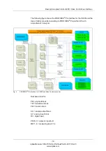
Page 16: ...terface for the C4000 and the Haze Control converter according to PROFIBUS PA profile 3 01 with amendment 2 Analyzer Fig 3 PROFIBUS PA interface for C4000 and Haze Control converter Numbers stand for PB physical block TB transducer block FB function block AO analog output block AI analog input block DI digital input PD IN X detector input A D MW 1 4 measuring result 1 4 ...

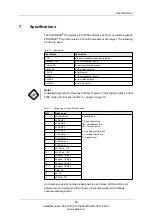
Page 17: ...al IEC 61158 2 31 25 kbit s voltage mode Connection polarity independent Voltage range 9 32 V Background current 18 mA Galvanic separation function separation Intrinsic safety no ID 0x0BF3 Address range 3 to 126 delivery state 126 Set_Slave_Adr of master Device profile PROFIBUS PA profile version 3 01 with amendment 2 Block structure 1 PB 4 AI with 1 TB each 4 DI with 1 TB 2 AO with 1 TB 1 status ...

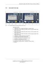
Page 18: ...xceeds or falls below a limit value 3 LED yellow switch indicator for alarm 2 when a value exceeds or falls below a limit value 4 LED yellow switch indicator for alarm 1 when a value exceeds or falls below a limit value 5 LED green indicates readiness for operation 6 Numerical keyboard single assignment 7 Connection for RS 232 control connect cable 8 ENTER key confirmation of entries 9 Cursor key ...

Page 19: ...ption 24 V AC DC T 3 15 A 12 Power supply fixed 13 Selector switch for voltage preset 230 V AC does not apply for a 24 V AC DC version 14 Equipotential bonding in the non ex proof version only necessary in extreme EMC requirements 15 ON OFF switch 16 17 Detector input C inactive 19 20 21 V DC 6 230V DETECTOR INPUTS C 3 4 5 3 4 5 D OPTEK DANULAT M6 PA L PE N R6 R8 RR R7 R2 R5 R4 R3 R1 MADE IN GERMA...

Page 20: ...4 V AC DC T 3 15 A 12 Power supply fixed 13 Selector switch for voltage preset 230 V AC does not apply for a 24 V AC DC version 14 Equipotential bonding in the non ex proof version only necessary in extreme EMC requirements 15 ON OFF switch 16 17 Detector input C only for optek sensors 19 20 21 V DC 6 230V DETECTOR INPUTS C 3 4 5 3 4 5 D OPTEK DANULAT M6 PA L PE N R6 R8 RR R7 R2 R5 R4 R3 R1 MADE I...

Page 21: ... II 115 230 V AC T 1 6 A option 24 V AC DC T 3 15 A 12 Power supply fixed 13 Selector switch for voltage preset 230 V AC does not apply for a 24 V AC DC version 14 Equipotential bonding in the non ex proof version only necessary in extreme EMC requirements 15 ON OFF switch 16 17 Detector input C only for optek sensors 21 20 19 DETECTOR INPUTS DETECTOR INPUTS C 5 4 3 A 1 5 2 5 4 3 D B 1 5 2 OPTEK D...

Page 22: ... Fuse II 115 230 V AC T 1 6 A option 24 V AC DC T 3 15 A 12 Power supply fixed 13 Selector switch for voltage preset 230 V AC does not apply for a 24 V AC DC version 14 Equipotential bonding in the non ex proof version only necessary in extreme EMC requirements 15 ON OFF switch 16 Detector input D inactive 17 Detector input C only for optek sensors 20 21 19 DETECTOR INPUTS C 3 4 5 3 4 D 5 DETECTOR...

Page 23: ...I 115 230 V AC T 1 6 A option 24 V AC DC T 3 15 A 12 Power supply fixed 13 Selector switch for voltage preset 230 V AC does not apply for a 24 V AC DC version 14 Equipotential bonding in the non ex proof version only necessary in extreme EMC requirements 15 ON OFF switch 16 Detector input D only for optek sensors 17 Detector input C only for optek sensors 20 21 19 DETECTOR INPUTS C 3 4 5 3 4 D 5 D...

Page 24: ...tion 24 V AC DC T 3 15 A 12 Power supply fixed 13 Selector switch for voltage preset 230 V AC does not apply for a 24 V AC DC version 14 Equipotential bonding in the non ex proof version only necessary in extreme EMC requirements 15 ON OFF switch 16 Detector input D inactive 17 Detector input C only for optek sensors 20 21 19 DETECTOR INPUTS C 3 4 5 3 4 D 5 DETECTOR INPUTS A 2 5 1 2 5 1 B OPTEK DA...

Page 25: ...II 115 230 V AC T 1 6 A option 24 V AC DC T 3 15 A 12 Power supply fixed 13 Selector switch for voltage preset 230 V AC does not apply for a 24 V AC DC version 14 Equipotential bonding in the non ex proof version only necessary in extreme EMC requirements 15 ON OFF switch 16 Detector input D only for optek sensors 17 Detector input C only for optek sensors 20 21 19 DETECTOR INPUTS C 3 4 5 3 4 D 5 ...

Page 26: ... Connecting the sensors Danger Electrical voltage Switch the converter voltage free before connecting the sensor Have electrical connections installed only by qualified electricians An overview of the connections of our sensors as well as of the wiring plans is provided in the supplied standard instruction manual of the converter ...

Page 27: ...able have different colors Usually red B conductor and green A conductor are used However other colors can be used as well Tool Screw driver Fig 12 Fieldbus terminals PROFIBUS PA with connector The fieldbus is connected to the supply terminals of the device terminals 51 54 grounding terminal 51 54 cable red B conductor terminal 52 cable green A conductor terminal 53 The connection to the PROFIBUS ...

Page 28: ...of hardware DIP switches the manufacturer s device software or the master control system 6 3 Addressing via the master control system The optek PROFIBUS PA interface for C4000 and Haze Control converters only supports the setting of the slave address by means of the Profibus DP service Set_Slave_Adr SAP55 via a DPM2 master DP master class 2 Fig 13 Schematic structure of an addressing network Thus ...

Page 29: ...upler DP PA link Siemens Pepperl Fuchs DP PA segment coupler segment coupler transparent in DP net max 124 slaves possible transfer rate 45 45 kbit s address range for slaves 3 125 DPV1 compatible cyclic acyclic Segment coupler SK1 segment coupler transparent in DP net max 124 slaves possible transfer rate 93 75 kbit s address range for slaves 3 125 DPV1 compatible cyclic acyclic DP PA link multis...

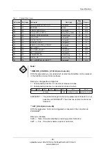
Page 30: ...evice info User blocks Description 1 PB with device specific expansion features 4 analyzer TBs for four measuring results 1 status TB for device status information 1 relay TB for four relay outputs 1 AO TB for mA inputs 4 AI FBs for four measuring results 4 DI FBs for four relay outputs 2 AO FBs for two mA inputs Tab 6 Assignment of the different blocks Slot Block name 0 Physical Block Abbreviatio...

Page 31: ...gned8 1 R W 5 21 TARGET_MODE Unsigned8 1 R W 6 22 BLOCK_MODE DS 37 3 R Actual Unsigned8 1 Permitted Unsigned8 1 Normal Unsigned8 1 7 23 ALARM_SUM DS 42 8 R Current Octet String 10 2 Unacknowledged Octet String 10 2 Unreported Octet String 10 2 Disabled Octet String 10 2 8 24 SOFTWARE_REVISION Visible String 16 R 9 25 HARDWARE_REVISION Visible String 16 R 10 26 DEVICE_MAN_ID Unsigned16 2 R 11 27 DE...

Page 32: ... 0x00 false Converter disables an existing system hold state 0xFF true Converter enables a system hold state 24 40 IDENT_NUMBER_SELECTOR Unsigned8 1 R W 26 42 FEATURE DS 68 8 R W 27 43 COND_STATUS_DIAG Unsigned8 1 R W 28 44 DIAG_EVENT_SWITCH Diag_Event_Switch 50 R W 36 52 DEVICE_CONFIGURATION Visible String 32 R 37 53 INIT_STATE Unsigned8 1 R W 38 54 DEVICE_STATE Unsigned8 1 R W 39 55 GLOBAL_STATU...

Page 33: ...02 0x0B00 Read in zero point for measuring results M01 M02 and M04 SET_PRODUCT slot index 67 With this parameter you can load a configured product in the converter Data type Unsigned16 High byte 0x01 change to product 1 0x02 change to product 2 0x03 change to product 3 0x04 change to product 4 0x05 change to product 5 0x06 change to product 6 0x07 change to product 7 0x08 change to product 8 Low b...

Page 34: ...tically mapped on BAD state BIT 1 to BIT 6 serves for masking enhanced optek specific diagnosis information 0 The corresponding diagnosis information is not displayed in DIAGNOSIS_EXTENSION 1 The corresponding diagnosis information is displayed in DIAGNOSIS_EXTENSION The setting is maintained after a restart of the device Delivery state 0x00 BIT 7 BIT 6 BIT 5 BIT 4 BIT 3 BIT 2 BIT 1 BIT 0 mask bit...

Page 35: ...16 2 R 2 18 TAG_DESC Octet String 32 R W 3 19 STRATEGY Unsigned16 2 R W 4 20 ALERT_KEY Unsigned8 1 R W 5 21 TARGET_MODE Unsigned8 1 R W 6 22 BLOCK_MODE DS 37 3 R 7 23 ALARM_SUM DS 42 8 R 8 24 COMPONENT_NAME Octet String 32 R W 9 25 PV DS 60 12 R PV Floating point 4 MEASUREMENT_STATUS Unsigned8 1 PV_TIME Date 7 10 26 PV_UNIT Unsigned16 2 R W 11 27 PV_UNIT_TEXT Octet String 8 R W 12 28 ACTIVE_RANGE ...

Page 36: ...67 10 R W BATCH_ID Unsigned32 4 RUP Unsigned16 2 OPERATION Unsigned16 2 PHASE Unsigned16 2 10 26 OUT DS 33 5 R VALUE Float32 4 STATUS Unsigned8 1 11 27 PV_SCALE Float 8 R W 12 28 OUT_SCALE DS 36 11 R W EU at 100 Float 4 EU at 0 Float 4 UNITS INDEX Unsigned16 2 DECIMAL POINT Integer8 1 13 29 LIN_TYPE Unsigned8 1 R W 14 30 CHANNEL Unsigned16 2 R W 16 32 PV_FTIME Float 4 R W 17 33 FSAFE_TYPE Unsigned...

Page 37: ... 2 R 2 18 TAG_DESC Octet String 32 R W 3 19 STRATEGY Unsigned16 2 R W 4 20 ALERT_KEY Unsigned8 1 R W 5 21 TARGET_MODE Unsigned8 1 R W 6 22 BLOCK_MODE DS 37 3 R 7 23 ALARM_SUM DS 42 8 R 12 28 PV_D_1 DS 34 2 R Value Unsigned8 1 Status Unsigned8 1 23 39 PV_D_2 DS 34 2 R Value Unsigned8 1 Status Unsigned8 1 24 40 PV_D_3 DS 34 2 R Value Unsigned8 1 Status Unsigned8 1 25 41 PV_D_4 DS 34 2 R Value Unsign...

Page 38: ... ALERT_KEY Unsigned8 1 R W 5 21 TARGET_MODE Unsigned8 1 R W 6 22 BLOCK_MODE DS 37 3 R 7 23 ALARM_SUM DS 42 8 R 8 24 BATCH DS 67 10 R W BATCH_ID Unsigned32 4 RUP Unsigned16 2 OPERATION Unsigned16 2 PHASE Unsigned16 2 10 26 OUT_D DS 34 2 R W VALUE Unsigned8 1 STATUS Unsigned8 1 14 30 CHANNEL Unsigned16 2 R W 15 31 INVERT Unsigned8 1 R W 20 36 FSAFE_TYPE Unsigned8 1 R W 21 37 FSAFE_VAL_D Unsigned8 1 ...

Page 39: ...2 20 R 1 17 ST_REV Unsigned16 2 R 2 18 TAG_DESC Octet String 32 R W 3 19 STRATEGY Unsigned16 2 R W 4 20 ALERT_KEY Unsigned8 1 R W 5 21 TARGET_MODE Unsigned8 1 R W 6 22 BLOCK_MODE DS 37 3 R 7 23 ALARM_SUM DS 42 8 R 80 96 PV_1 DS 60 12 R PV Floating point 4 MEASUREMENT_STATUS Unsigned8 1 PV_TIME Date 7 81 97 PV_2 DS 60 12 R PV Floating point 4 MEASUREMENT_STATUS Unsigned8 1 PV_TIME Date 7 ...

Page 40: ...ERATION Unsigned16 2 PHASE Unsigned16 2 10 26 SP DS 33 5 R W VALUE Float32 4 STATUS Unsigned8 1 11 27 PV_SCALE Float 8 R W EU at 100 Float 4 EU at 0 Float 4 UNITS INDEX Unsigned16 2 DECIMAL POINT Integer8 1 12 28 READBACK DS 33 5 R VALUE Float32 4 STATUS Unsigned8 1 21 37 IN_CHANNEL Unsigned16 2 R W 22 38 OUT_CHANNEL Unsigned16 2 R W 23 39 FSAFE_TIME Float 4 R W 24 40 FSAFE_TYPE Unsigned8 1 R W 25...

Page 41: ... correspond to 0 100 0 1 here 37 53 OUT DS 33 5 R W VALUE Float32 4 STATUS Unsigned8 1 38 54 OUT_SCALE Float 8 R W EU at 100 Float 4 EU at 0 Float 4 UNITS INDEX Unsigned16 2 DECIMAL POINT Integer8 1 Tab 13 AO FB for mA In1 and mA In2 cont Rel Index Slot index Parameter Data type Size bytes Access ...

Page 42: ...ctet String 24 R 13 29 INFO_ADDRESS_5 Octet String 24 R 14 30 CONFIGURATION_STATUS Unsigned8 1 R 15 31 SET_LAMP_CHANNEL Unsigned16 1 R W 16 32 STATUS_LAMP DS LAMP 10 R LAMP_ON Boolean 1 SENSOR_ON_LAMP Unsigned8 1 LAMP_VOLTAGE_ V Float 4 LAMP_CURRENT_ mA Float 4 17 33 DETECTOR_MONITOR DS DETECTOR 16 R PHOTO_CURRENT_ nA Float 4 ZERO_CURRENT_ nA Float 4 PHOTO_CURRENT_ CU Float 4 PHOTO_CURRENT_ISA_ CU...

Page 43: ...spond to the values of the corresponding monitor Data type Unsigned16 High byte In the high or low nibble no more than 1 bit shall be set If 0x00 is transferred as information the information of LAMP E and CHANNEL A is written into the corresponding registers Low byte Upon writing the parameter the low byte value can be any value from 0 to 255 For reading the parameter the following applies 0x__00...

Page 44: ... window locally at the converter the parameter is set to zero and the error number cannot be read via PROFIBUS anymore SENSOR_INFO slot index 36 According to the selected channel slot index 31 with this parameter the sensor serial number and type can be read For that the information must be defined in the system settings for the corresponding sensor For a Haze Control with PROFIBUS interface both ...

Page 45: ...1 3 LAMP_VOLTAGE_ V Float 4 4 LAMP_CURRENT_ mA Float 4 71 DS DETECTOR 1 PHOTO_CURRENT_ nA Float 4 2 ZERO_CURRENT_ nA Float 4 3 PHOTO_CURRENT_ CU Float 4 4 PHOTO_CURRENT_ISA_ CU Float 4 72 DS_P_Name 1 PRODUCT_1 Visible String 12 2 PRODUCT_2 Visible String 12 3 PRODUCT_3 Visible String 12 4 PRODUCT_4 Visible String 12 5 PRODUCT_5 Visible String 12 6 PRODUCT_6 Visible String 12 7 PRODUCT_7 Visible St...

Page 46: ... 0 HW failure 1 0 DIA_HW_ELECTR 1 1 DIA_HW_MECH 2 2 DIA_TEMP_MOTOR 3 Flag when Error 1402 TEMP_HI occurs 3 DIA_TEMP_ELECTR 4 4 DIA_MEM_CHKSUM 5 5 DIA_MEASUREMENT 6 6 DIA_NOT_INIT 7 7 DIA_INIT_ERR 8 2 0 DIA_ZERO_ERR 9 1 DIA_SUPPLY 10 2 DIA_CONF_INVAL 11 3 DIA_WARMSTART 12 4 DIA_COLDSTART 13 5 DIA_MAINTENANCE 14 6 DIA_CHARACT 15 7 IDENT_NUMBER_VIOLATION 16 reserved by PNO 3 0 reserved by PNO 17 1 18...

Page 47: ...cation Please contact us Please find our contact details in chapter 11 page 60 If this diagnosis is signaled the converter may currently be switched off or booting If this is not the case there can be a problem with internal data communication Please contact us Please find our contact details in chapter 11 page 60 32 ERROR NUMBER AVAILABLE 1 0 optek internal error code in Status TB available 33 SI...

Page 48: ...uality substatus Limits Hex value Meaning 0 Good G Good 1 0 0 0 0 0 0 0 0x80 Good OK 0 Good G Good 1 0 0 0 0 0 x x 0x84 0x87 Good update event 0 Good G Good 1 0 0 0 1 0 0 1 0x89 Good advisory alarm low limit 0 Good G Good 1 0 0 0 1 0 1 0 0x8A Good advisory alarm high limit 0 Good G Good 1 0 0 0 1 1 0 1 0x8D Good critical alarm low limit 0 Good G Good 1 0 0 0 1 1 1 0 0x8E Good critical alarm high l...

Page 49: ...com Specifications 7 12 Number display format All float values are indicated according to float format ieee754 Tab 18 Number display format 31 BYTE0 24 23 BYTE1 16 15 BYTE2 8 7 BYTE3 1 V E E E E E E E E M M M M M M M M M M M M M M M M M M M M M M M exponent mantissa ...

Page 50: ... instructions in the host supplier manual for installing the required GSD file in the PLC 8 2 EDD file EDD stands for Electronic Device Description and is some kind of parameterization file in which the standard description of the used blocks is stored EDD Electronic Device Description 40000BF3_edd zip 8 3 FDT DTM technology The FDT Field Device Tool technology standardizes the communication and c...

Page 51: ...Appendix 47 optek Manual 1004 1010 02 ProfibusPA US 2017 06 23 www optek com 9 Appendix ...

Page 52: ...g a corresponding Profibus DP service Set_Slave_Adr SAP55 Below you will find only a small selection If there is no solution listed for your system we kindly ask you to contact the manufacturer of your Profibus master environment PC PG with communication processor manufacturer Siemens using Siemens software similar to CP5512 CP 5603 CP 5611 A2 CP 5613 A2 CP 5614 A2 CP 5621 CP 5711 CP 5623 CP 5624 ...

Page 53: ...ndix 49 optek Manual 1004 1010 02 ProfibusPA US 2017 06 23 www optek com Omron CS1 CJ1W PRM21 Profibus master unit optek DTM driver is needed Fig 15 Addressing via Omron CS1 CJ1W PRM21 Profibus master unit ...

Page 54: ...ith communication processor CP5512 DPM2 master implementation tested with the help of PC PG with communication processor Siemens CP5512 software used SIMATIC Manager 1 Start the SIMATIC Manager software 2 Go to Options and open the window Set PG PC Interface Fig 16 Set PG PC Interface menu Select the access point CP5512 PROFIBUS In the properties window select the option PG PC is the only master o...

Page 55: ...017 06 23 www optek com 4 Enter a new address for the slave device e g 16 and confirm with OK Fig 18 Entering a new PROFIBUS address 5 For testing purposes the setting of a new address can be checked by means of a LifeList Fig 19 Checking the new address ...

Page 56: ...IMATIC Manager with the single channel USB interface card Softing PROFIusb DPM2 master implementation tested with the help of PROFIBUS master single channel USB interface card Softing PROFIusb software used SIMATIC Manager and SIMATIC PDM 1 Start the SIMATIC Manager software 2 Go to Options and open the window Set PG PC Interface Fig 20 Set PG PC Interface menu Select the access point Softing PROF...

Page 57: ...3 Start the SIMATIC PDM LifeList Note Slaves with the address 126 are not displayed Fig 21 SIMATIC PDM LifeList For address 3 Open object 4 Under SIMATIC PDM PROFIBUS PA add a new device Fig 22 SIMATIC PDM PROFIBUS PA adding a device 5 Select C HC_4xxx Fig 23 Selecting C HC_4xxx ...

Page 58: ...vice open the menu Assign address Fig 24 Assigning an address 7 Enter a new address for the slave device e g 16 and confirm with OK Fig 25 Assigning an address The potential error message Error during node initialization can be ignored Fig 26 Error message Error during node initialization ...

Page 59: ...Appendix 55 optek Manual 1004 1010 02 ProfibusPA US 2017 06 23 www optek com 8 For testing purposes the setting of a new address can be checked by means of a LifeList Fig 27 Checking the new address ...

Page 60: ...Appendix 56 optek Manual 1004 1010 02 ProfibusPA US 2017 06 23 www optek com 9 2 PROFIBUS PA certificate Fig 28 PROFIBUS PA certificate ...

Page 61: ... successfully the tests for Device Type Managers Test report Nr 2011 011 0051 Date of Test June 20 2012 Tested device type C HC_4XXX Version 1 0 0 dtmINSPECTOR version 3 0 0 1300 Operating system Windows XP 5 1 2600 Service Pack 3 Required communication protocol Profibus DPV1 Tested communication protocol Profibus DPV1 Style guide conformity tested on optek Danulat GmbH has declared with written s...

Page 62: ...he FDT Certified label and logo in the product specification and marketing communication of tested and supported device types A high resolution version of this logo is available from the FDT Business Office Jodoigne August 20 2012 Katrien Peeters FDT Certification Office Supported devices types for which this certificate is granted Supported operation systems types for which this certificate is gr...

Page 63: ...ith X 0 8 Haze Control HC 4XXX X 0 6 as well as one sensor of the series AF16 AF26 AF45 AF46 TF16 N DTF16 ASD12 ASD19 ASD25 AS16 AS56 ACF60 ACS60 have been developed constructed and manufactured in conformity with the requirements of EU directives 2014 35 EU 2014 30 EU published in L96 of 29 03 2014 2011 65 EU published in L174 of 01 07 2011 The assessment is based on the application of the standa...

Page 64: ...nc N118 W18748 Bunsen Drive Germantown WI 53022 USA Phone 1 262 437 3600 Toll free call 1 800 371 4288 Fax 1 262 437 3699 E Mail info optek com China optek Danulat Shanghai Co Ltd Room 718 Building 1 No 88 Keyuan Road Pudong Zhangjiang Shanghai China 201203 Phone 86 21 2898 6326 Fax 86 21 2898 6325 E Mail info optek danulat cn 中国 优培德在线测量设备 上海 有限公司 上海张江科苑路 88 号德国中心 718 室 邮编 201203 电话 86 21 28986326...

Reviews: