background image

Notice 

d’utilisation 

du 

transmetteur 

Audio/Vidéo 

2,4GHz 

     Page 

21

G. Troubleshooting, Care and Maintenance

Please read this owner’s manual carefully and follow the steps described in it.  If you still have dif-

fi

 culties, consult the following table.  It will guide you though the most common problems and their 

solutions.

Problem

Possibles solutions

No picture or sound

• Check the power on/off switches on the trans-
mitter and receiver
• Check power switches on the remote TV and 
video source (VCR, laser disc player, satellite 
receiver, ect.)
• Make sure power plugs are pushed all the 
way in 
 • Check all cable connections

Interference:
Noisy picture or audio

• Adjust receiver and transmitter antenna orien-
tation
• Select a different channel by pushing the 
channel selector switch on both transmitter and 
receiver so that the channels match
• If using a microwave oven, turn it off
• Remove microwave oven from path between 
transmitter and receiver.

Remote control does not work

• Check the path between the transmitter and 
the audio/video source and clear any obstruc-
tions.

H. TECHNICALS FEATURES

Transmitter :

    Output Level
    Operating Frequency Band Modulation
    Video Input Level
    Audio Input Level
    Video Input Impedance
    Audio Input Impedance
    Power consumption
    Operation Temperature
    Dimensions    
    Weight

90 dB µV/meter at 3 m (comply with FCC, BZT)
2.4 to 2.4835 GHZ FM (video and audio)
1V p-p @ 75 ohms
2V p-p @ 600 ohms
75 ohms
600 ohms
9 Vdc, 150 mA
0°C~50°C (Indoor use only)
17.8 X 12.6 X 6 cm
286g

Receiver :

    Output Level
    Power Consumption
    Frequency
    Operation Temperature
    Dimensions
    Weight

1 Vp-p @75 ohms (video), 3 volt p-p (audio)
9 Vdc, 280 mA
433.92 MHz (BZT, FCC)
0°~50°C (Indoor use only)
17.8 X 12.6 X 6 cm
312g

Summary of Contents for 750830

Page 1: ...TRANSMETTEURAUDIO VIDEO 2 4GHz TRANSMETTEURAUDIO VIDEO 2 4GHz REF 750830 avec extension infra rouge www optex fr...

Page 2: ......

Page 3: ...tre les interf rences dans les installations r sidentielles Cet quipement g n re et peut mettre des fr quences radios s il n est pas install et utilis conform ment aux instructions il risque alors de...

Page 4: ...e l utilisation de la large bande FM plut t que la modulation de signal AM Les antennes des r cepteurs et des metteurs sont utilis es pour diminuer les interf rences non d sir es sur le signal et augm...

Page 5: ...teur pour le transformateur Connecteur RCA jaune pour la vid o Connecteur RCA rouge Audio droit Connecteur RCA blanc Audio gauche Switch de s lection de canal utilis pour une r ception opti male Il es...

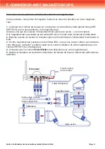
Page 6: ...es Vid o Magn toscope C ble avec sortie A V R cepteur satellite Lecteur DVD ou CDROM Camescope Ordinateur Sources Audio Lecteur de disque compact ou changeur R cepteur st r o Lecteur cassette Les page...

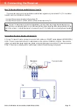
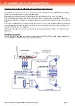
Page 7: ...ormateur d alimentation fournit dans la bo te 3 Si votre magn toscope poss de une des fiches RCA et que vous voulez l utiliser proximit de votre t l viseur connecter un c ble coaxial sur la sortie mod...

Page 8: ...e l cran une autre image comme celle de votre b b entrain de dormir Consulter le manuel de votre t l viseur pour voir l utilisation de cette fonction Connecter le r cepteur directement au t l viseur l...

Page 9: ...alors connecter le c ble blanc 2 Brancher ensuite sur secteur le r cepteur gr ce au transformateur d alimentation fournit dans la bo te 3 Si votre magn toscope poss de une des fiches RCA et que vous v...

Page 10: ...cepteur afin d obtenir la meilleure image possible Si vous utilisez un micro onde teignez le Si un micro onde est dans la trajectoire de l metteur et du r cepteur enlevez le La t l commande ne r pond...

Page 11: ...Soci t NORMAND OPTEX Zone industrielle du Pommier Boulevard Eug ne Thomas 62110 H nin Beaumont www optex fr...

Page 12: ...2 4GHz WIRELESS AUDIO VIDEOSENDER 2 4GHz WIRELESS AUDIO VIDEOSENDER REF 750830 OWNER S MANUAL www optex fr...

Page 13: ......

Page 14: ...cause harmful inter ference to radio communications However there is no guarantee that interference will not occur in a particular installation If this equipment does cause harmful interference to rad...

Page 15: ...ters It s superior quality is due to wide band FM rather than AM signal modulation Circular polarized high gain directional transmitting and receiving antennas are used to minimize interference from u...

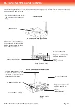
Page 16: ...nal Hi ding Power on LED Power on off switch DC power input connect to power adapter 9v Video Jack yellow out Audio Right out red Audio Left out white Channel selection switch use to find optimal rece...

Page 17: ...onnect to following A V equipment use Video sources VCR Cable set top box with A V output Satellite Receiver Laser Disc Player or DVD Player Camcorder or Miniature CCD Camera Computer Audio sources Co...

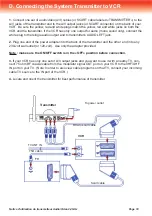
Page 18: ...s AUDIO LEFT jack 2 Plug one end of the power adapter into the back of the transmitter and the other end into any 230 volt wall outlet or 120 volt Use only the adapter provided Note make sure the ON...

Page 19: ...ed by sys tem such as your sleeping baby in a small inset picture while enjoying other programming on the rest of the screen Consult the owner s manual of your TV for instructions on using these capab...

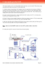
Page 20: ...nd white jacks on both the system receiver and the VCR If the VCR has only a single jack for audio input connect the white plug to it 2 If your TV has A V input jacks connect another set of A V cables...

Page 21: ...he channel selector switch on both transmitter and receiver so that the channels match If using a microwave oven turn it off Remove microwave oven from path between transmitter and receiver Remote con...

Page 22: ...Soci t NORMAND OPTEX Zone industrielle du Pommier Boulevard Eug ne Thomas 62110 H nin Beaumont www optex fr...

Reviews: