2
System structure
2-1
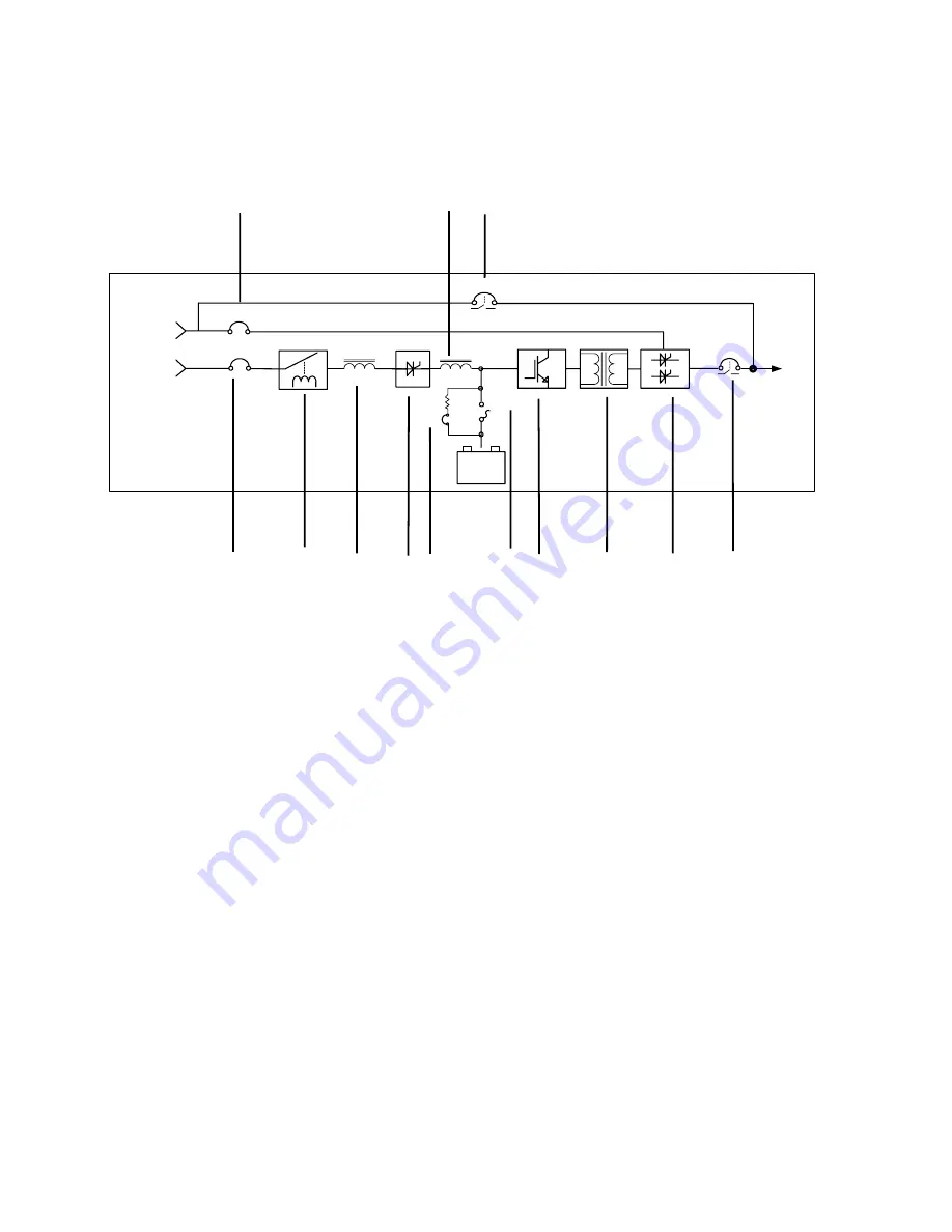
System Diagram of DS-C33
(12) (5) (7)
Load
Battery
Pack
+
-
S3
S6
S4
S5
S1
Utility 1
Utility 2
S2
(1) (2) (3) (4) (13) (6)
(8) (9) (10) (11)
fig. 2-1
(1)
Main power switch (S3)
(2)
Input protection
(3)
Three phase alternating current power inductor
(4)
Rectifier / battery charger module
(5)
Direct current power inductor
(6)
Battery fuse switch (S4)
(7)
Manual bypass switch (S6)
(8)
Inverter module
(9)
Isolation transformer
(10)
Static switch module
(11)
Output switch (S5)
(12)
Bypass power switch (S2)
(13)
Start up auxiliary switch (S1)
Note :
(1)The UPS input can be powered from a single utility source or by dual utility sources.
(2)Dual utility input is optional.
Summary of Contents for DS-C33 100K
Page 1: ......
Page 7: ...Drawings 2 2C and 2 2D are the assembly diagrams of DS C33 series 45K 60K 80K Fig 2 2C ...
Page 8: ...Fig 2 2D ...
Page 9: ...Drawings 2 2E and 2 2F are the assembly diagrams of DS C33 series 22 5K 30K Fig 2 2E ...
Page 10: ...Fig 2 2F ...
Page 11: ...Drawings 2 2G and 2 2H are assembly diagrams of DS C33 series 10K 15K Fig 2 2G ...
Page 12: ...Fig 2 2H ...
Page 28: ...TIME SET DATE 200 TIME F 1 Date Time Set Y M D 200 H M S Succeed ...
Page 38: ...Fig 5 1 1 ...
Page 40: ...Fig 5 3 ...


