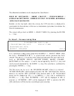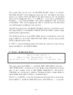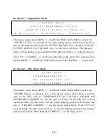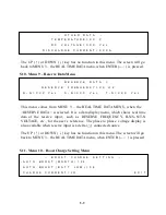
5-12
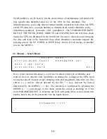
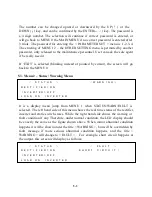
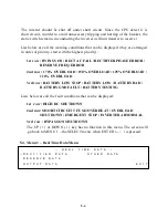
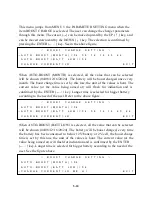
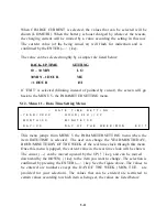
- YEAR : 1998 – 2097
- MONTH : 01-12
- DAY : 01 – 31
(internal calendar will correct it if 31 is entered to a 30day
month)
- HOUR : 0 – 23
- MINUTE : 0 - 59
- DAY OF THE WEEK : MON, TUE, WED, THU, FRI, SAT, SUN
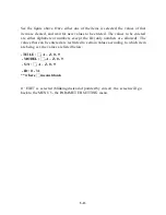
The value can be increased upward by the UP (
↑
) key, and can be decreased
downward by the DOWN (
↓
) key. The value will flash if it is being set, you can
continue to push the UP(
↑
) or the DOWN (
↓
) key until the expected value is
displayed. Again, the selection is confirmed by pressing the ENTER(
←┘
) key.
Then the values in the real clock will be changed according to the values you
enter, and the real time will continue to run base on these values.
If ‘EXIT’ is selected (blinking instead of pointed by cursor), the screen will go
back to the MENU 5- the PARAMETER SETTING menu.
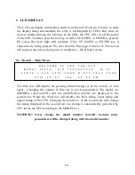
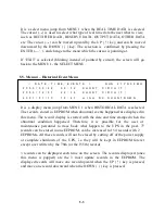
5.13. Menu 12 – Other Setting Menu
→
T I T L E :
<
O T H E R
S E T T I N G
>
X X X X X X X X X X X X X X X X X X X X X X X X X X X X X X X X X X X X X X X X
M O D E L : X X X X X X
S
/
N : X X X X X X X X X X
I D : X X
E X I T
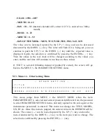
This menu jumps from MENU 1 the SELECT MENU when the item
PARAMETER SET is selected and correct password (different from the password
to enter PARAMETER SETTING menu, and only opened to the sole agent or the
maintenance personnel) is entered. This menu can change the TITLE, MODEL,
S/N, ID etc. Once this menu is popped, the current value in the EEPROM will be
shown. The cursor (
→
) can be moved upward by the UP (
↑
) key, and can be
moved downward by the DOWN (
↓
) key to the item you want to change. The
selection is confirmed by pressing the ENTER (
←┘
) key.
Summary of Contents for DS-D33
Page 1: ...OPTI UPS User s Guide Durable Series Models DS D33 www opti ups com ...
Page 16: ...1 12 1 7 Dimension Drawings 20KVA 60KVA OUTLINE DRAWING ...
Page 17: ...1 13 20KVA 60KVA INTERIOR DRAWING ...
Page 18: ...1 14 80KVA 160KVA OUTLINE DRAWING ...
Page 19: ...1 15 80KVA 160KVA INTERIOR DRAWING ...
Page 20: ...1 16 200KVA 320KVA OUTLINE DRAWING ...
Page 21: ...1 17 200KVA 320KVA INTERIOR DRAWING ...
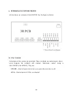
Page 22: ...1 18 INTER PCB DIAGRAM ...

