8-2
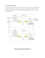
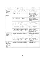
The two UPSs are running in normal mode currently under normal conditions.
When one of them has problem, the load will still has protection from inverter
and battery. If UPS1 fail and UPS2 is running normally, the load is unaffectedly
supplied from UPS2. If UPS2 fail and UPS1 is running normally, UPS2 will
transfer the load to UPS1 and the load will continue to be protected by inverter
and battery of UPS1. If both of them are running normally, UPS2 takes up all load
and UPS1 bears no load. Therefore, UPS1 has a longer MTBF than UPS2 (can be
interchanged after a period of time), and their MTBF multiple to a large MTBF.
This type of redundancy is employed most frequently. Besides, when mains fail,
UPS2 is the first to contribute its battery to back-up the load, and when UPS2’s
battery is exhausted, the load will be transferred to UPS1, and now UPS1 start to
contribute its battery. Therefore, this topology can make full use of the battery.
The user will not feel wasting money in buy two UPS, for he get a system that has
double protection and double back-up time.
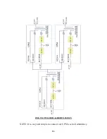
Another cheaper solution (see the figure next page) is if your load is separated,
you intended to install two UPSs with the same power; you can buy another UPS
as redundancy to two UPSs. The reason is that it is very rare that both UPSs
(UPS2 & UPS3) breakdown at the same time. Therefore, UPS1 can be a hot
standby UPS to two UPSs.
Anywhere, this topology already makes full use of its resources to contribute the
best protection and longest MTBF.
Summary of Contents for DS-D33
Page 1: ...OPTI UPS User s Guide Durable Series Models DS D33 www opti ups com ...
Page 16: ...1 12 1 7 Dimension Drawings 20KVA 60KVA OUTLINE DRAWING ...
Page 17: ...1 13 20KVA 60KVA INTERIOR DRAWING ...
Page 18: ...1 14 80KVA 160KVA OUTLINE DRAWING ...
Page 19: ...1 15 80KVA 160KVA INTERIOR DRAWING ...
Page 20: ...1 16 200KVA 320KVA OUTLINE DRAWING ...
Page 21: ...1 17 200KVA 320KVA INTERIOR DRAWING ...
Page 22: ...1 18 INTER PCB DIAGRAM ...

