9-2
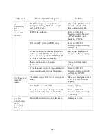
Abnormal
Description & Checkpoint
Solution
(4) The voltage
difference
between
NEUTRAL and
GROUND
become
abnormally
higher
﹖
There is external wiring error of R.S.T
phase and N. G. instead of UPS unit
itself,.
Correct the external wiring
system.
(5) The
inverter cannot
start up.
Apart from INVERTER SS LED in left
side of the front panel, there is other ones
still illuminate.
Do trouble shooting
according to the LED
instruction.
Switch on the inverter before DC bus has
been established completely. Normally, it
takes around 30 seconds to establish the
DC BUS since the reserve and rectifier
breakers are closed.
Refer to the switch on
procedure. Close the reserve
and rectifier breakers and
wait around 30 seconds or
directly use batteries to
establish the DC bus.
Bypass breaker has been closed (switched
on).
Open the bypass breaker.
The output is overloaded. The LCD will
display warning message ‘ XXX%
OVERLOAD’ in the STATUS/WARN
menu (MAIN menu
→
SELECT menu
→
STATUS/WARN menu). XXX%
OVERLOAD LED on left side of the
front panel and OVERLOAD LED on
right side will lit too.
Decrease the load to under
the UPS’s rated power.
In P&P modules1, the temperature sensor
sockets on 3G PCB and hest sink are not
connected properly. WARNINGLED of
FUSE/TEMP still illuminate but LED in
3G PCB doesn’t, indicating DC BUS may
be over 240VDC.
Take out the P&P module
and connect them properly.
Summary of Contents for DS-D33
Page 1: ...OPTI UPS User s Guide Durable Series Models DS D33 www opti ups com ...
Page 16: ...1 12 1 7 Dimension Drawings 20KVA 60KVA OUTLINE DRAWING ...
Page 17: ...1 13 20KVA 60KVA INTERIOR DRAWING ...
Page 18: ...1 14 80KVA 160KVA OUTLINE DRAWING ...
Page 19: ...1 15 80KVA 160KVA INTERIOR DRAWING ...
Page 20: ...1 16 200KVA 320KVA OUTLINE DRAWING ...
Page 21: ...1 17 200KVA 320KVA INTERIOR DRAWING ...
Page 22: ...1 18 INTER PCB DIAGRAM ...

