1-5
1.2. Features and Advantages
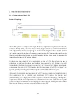
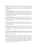
(a) Reliable input protection:
Circuit breakers is put in each individual input
loop to ensure power can continue through the other loop in case of breaker trip
caused abnormal condition in either rectifier or load.
(b) Input surge protection:
MOV (surge protector) is added at the input, provide
sufficient protection to both UPS and the load from any lightning or surge
caused by neighboring large loads.
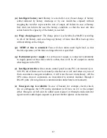
(c) EMI suppression:
EMI filter is added to meet the international EMC limits,
therefore, very low noise is emitted and never interfere other equipment
connected to the same AC source.
(d) Ruggedness:
The rectifier employ phase control technology to regulate the
DC bus voltage, so it can charge the battery directly, it is the most efficient
method to charge the battery. Besides, the component used is SCR, the
component get merits by its ruggedness under poor condition. Also, big inductor
is added at the input to avoid deforming the AC source waveform.
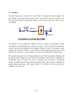
(e) High frequency design:
The inverter uses high frequency, high efficiency
IGBT, PWM method to convert the DC power to AC power. Therefore, number
of components is fewer, in return, reliability is improved, size and weight of
UPS is reduced, then the transportation cost is cheaper, performance improved
and the acoustic noise is eliminated too.
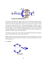
(f) True Galvanic isolation:
An isolated transformer is put at the output, can
solve the problem of poor input grounding and can accept a different ground
between input and output, can avoid the annoying problem of ground leakage
current and can be tied to any potential provided on site. The AC output is
isolated under every mode of operation. Besides, the user gets the bonus of
attenuation of common mode noise from the output isolation transformer.
Summary of Contents for DS-D33
Page 1: ...OPTI UPS User s Guide Durable Series Models DS D33 www opti ups com ...
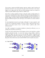
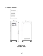
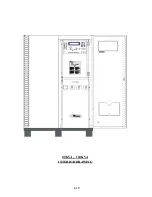
Page 16: ...1 12 1 7 Dimension Drawings 20KVA 60KVA OUTLINE DRAWING ...
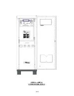
Page 17: ...1 13 20KVA 60KVA INTERIOR DRAWING ...
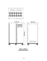
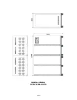
Page 18: ...1 14 80KVA 160KVA OUTLINE DRAWING ...
Page 19: ...1 15 80KVA 160KVA INTERIOR DRAWING ...
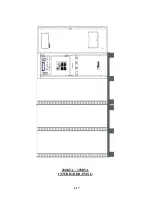
Page 20: ...1 16 200KVA 320KVA OUTLINE DRAWING ...
Page 21: ...1 17 200KVA 320KVA INTERIOR DRAWING ...
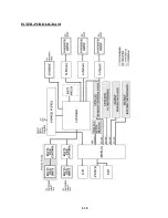
Page 22: ...1 18 INTER PCB DIAGRAM ...


