7
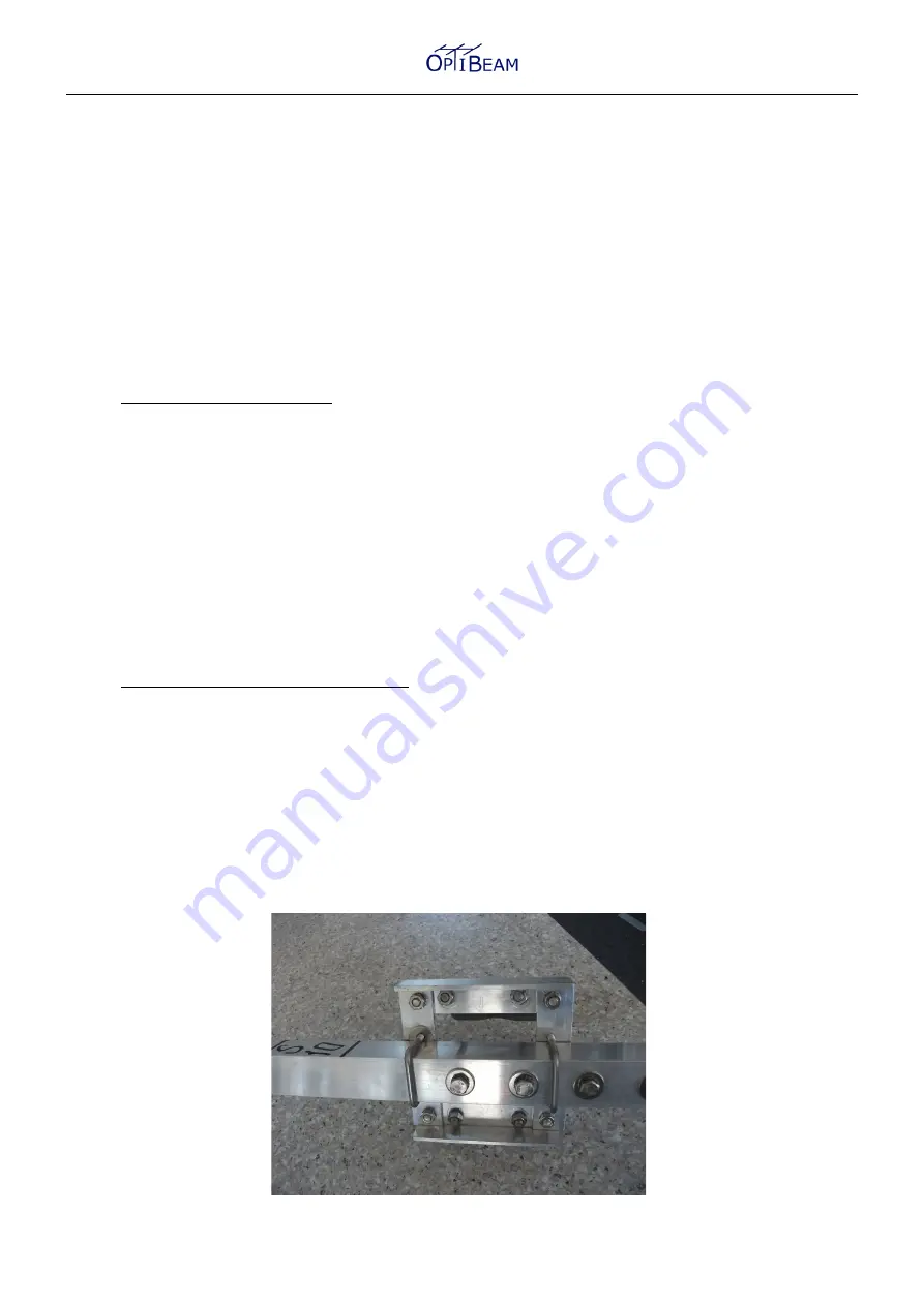
The plates are attached to the boom by 2 square brackets which embrace the boom from the top
and 4 self securing nuts (see picture page). When tightening the square brackets pay attention that
all elements are
parallel
to each other.
The driven elements (from the rear S10, S15, S20) should not be tightened before the installation
of the phase line is done (see fig. 2.5) as they might have to be moved slightly on the boom.
The plates of the outer elements end directly in line with the tips of the boom.
For convenience in general we recommend to assemble all element middle sections to the boom
first as well as the phase line (see fig. 2.5) and the coax socket should be connected to the drivers
within this step.
Afterwards the following element sections can be inserted and fixed.
2.5 Installation of the phase line
The driven elements (S10, S15, S20) are connected with 2 parallel 20mm square tubes (=phase
line).
The square tubes have to be in
direct contact
to the elements (put the washers only below the
screw heads). First remove the element screws and washers. Then insert the predrilled square
tubes (move the elements slightly if needed) by means of the element screws. Likewise insert the
coax connector at the bottom of the phase line (=elements below boom) directly with the screws of
S15 (see picture page). Be sure that the screw at the backsite of the connector which holds the
strap is
tightened solidely
.
Finally the phase line square tubes have to be
tightened really solidly
together with the driven
elements (=important electrical contact) and the driven elements have to be mounted below the
boom by means of the element plates (see fig. 2.4).
2.6 Installation of the boom to mast clamp
The boom to mast clamp is a completely pre assembled part.
It has to be attached close to the balance point of the antenna
between S10 and R15 as close as
possible to S10
.
To realize that locate the clamp in a way that the rear vertical right angle part runs exactly across
the boom transition.
This way the rear vertical right angle part of the clamp runs across the two big washers of the boom
transition hardware. This results in a different level between the clamp rear and front part.
To compensate this different level two big washers are used at the square bolt of the front vertical
right angle part of the clamp.
The entire construction can bee seen from the picture below.
Summary of Contents for OB6-3M
Page 10: ...9 ...


