OPTICAL SYSTEMS DESIGN
DOC ID: 10100306
OSD151 OPERATOR MANUAL
PAGE 9 OF 12
2.2.4
OTHER CONNECTIONS
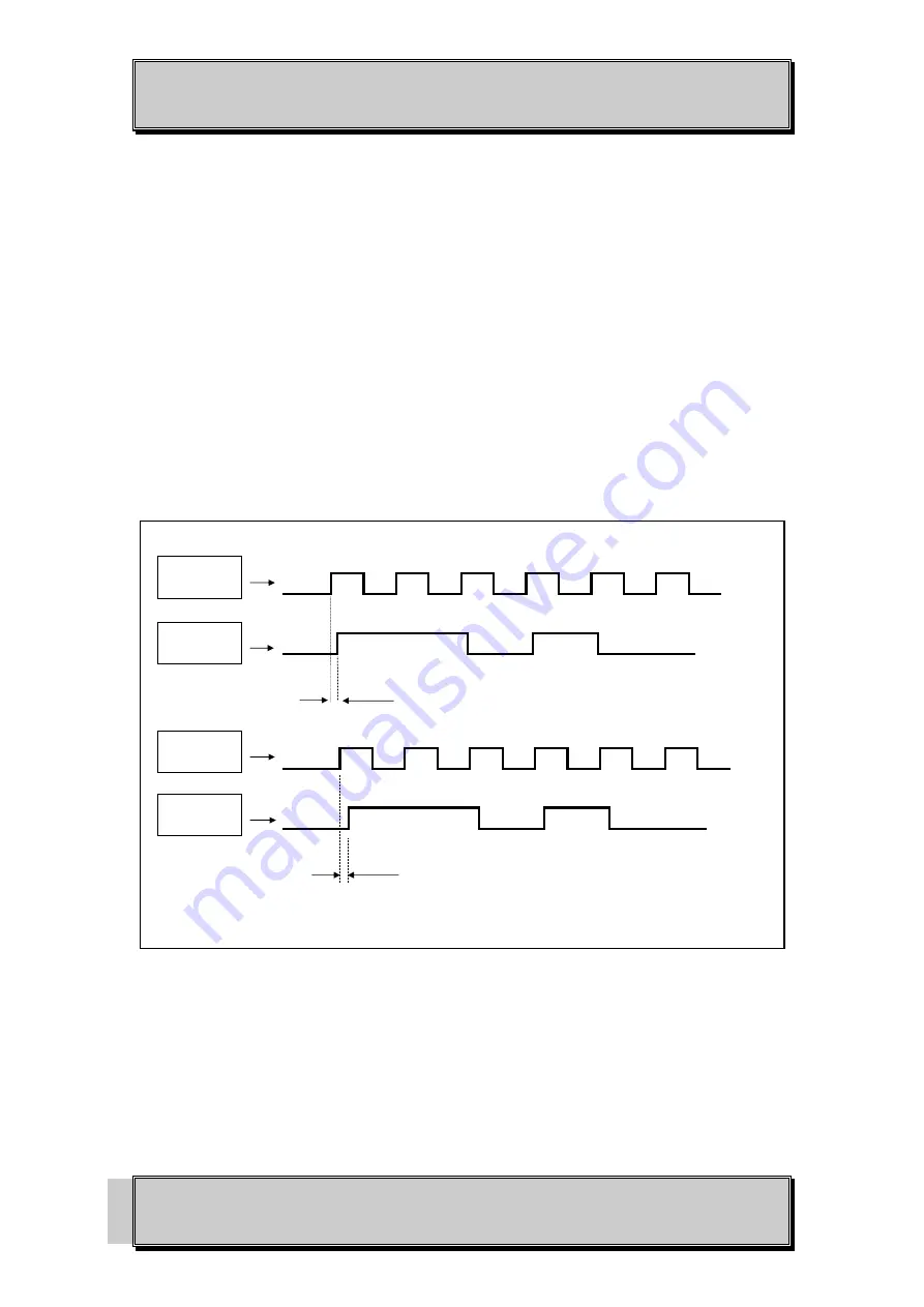
The RS422 signal is connected to or from external equipment by the 25 pin D connector. Ensure that
the incoming clock and data signals are correctly phased. The clock should go logically low at the
halfway point of the data bit.
Likewise ensure that the receiving equipment can accept the phasing of the clock and data signals
output from the OSD151 which has the clock going logically high about 15ns to 20ns before the data
bit. Refer to Figure 5 for more details.
+12V DC power is fed to the unit via pin 9 of this connector or via the power socket.
Each optical fiber must be terminated by an ST type optical connector. Before connection, inspect the
end of the connectors to ensure that no dust or dirt is present as it could contaminate the modem
connector and result in poor performance.
If it is necessary to clean the cable connectors use isopropyl alcohol and a lint free tissue to remove
contamination.
FIGURE 5: TIMING DIAGRAM
CLOCK
INPUT
DATA
INPUT
CLOCK
OUTPUT
DATA
OUTPUT
MUST BE
<50nS
TYPICALLY
15nS TO 20nS


