background image


OPTICAL SYSTEMS DESIGN 


DOC ID: 10112902 

OSD350B OPERATOR MANUAL


PAGE 3  


3


INSTALLATION AND OPERATION 


3.1


OSD921 POWER SUPPLY OPERATION 


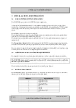
The OSD350B can use up to two OSD921 power supply units. 
 
A front panel mounted LED indicator on the OSD921 illuminates when the power supply unit is 
switched on.  Front panel test points are available on the OSD921 for monitoring the 12VDC output 
of the supply. Note that the test point outputs are current limited and cannot be used as a power 
source. 


The OSD921 supply has a built-in cooling fan. 
The cooling fan operates only when high temperatures are experienced on the power supply whilst 
under heavy load and/or high ambient temperatures. 
The fan may not continuously operate and under low load or low ambient temperatures it may not 
operate at all. 
 
The 

Temperature Alarm

 LED on the front panel of the OSD921 is green during normal operation 

and will be red when the operating temperature exceeds the normal operating limits of the supply. 
 
Do not continue to operate the power supply when the Temperature Alarm LED is red and take steps 
to rectify the cause of the excessive high temperature indication. 


3.2


IMPORTANT INSTALLATION REQUIREMENTS 

 
It is important to provide a cool operating environment as well as to provide adequate ventilation. 
 

The OSD350B chassis must be separated by at least a 1RU (about 44mm) gap above and below 
the unit to provide ventilation.


The ventilation holes of the chassis must never be covered by any objects. 


3.3


BACK PLANE OUTPUTS 

 
The OSD350B is merely a mechanical chassis, so electrical specifications are not given, other than 
the pin outs for the 9-pin D female connector of the back plane.


DB9 Pin 

Specification 

NMS Address Bit 1 

NMS Address Bit 2 

+12V

DC

 nominal 

NMS Address Bit 3 

D+ 

Ground 

Ground 

NMS Address Bit 4 

D- 


Summary of Contents for OSD350B

Page 1: ...OPERATOR MANUAL OSD350B 12 CARD CHASSIS WITH DUAL REDUNDANT POWER WITH OSD921 AND NMS...

Page 2: ......

Page 3: ...L DIMENSIONS 2 3 INSTALLATION AND OPERATION 3 3 1 OSD921 POWER SUPPLY OPERATION 3 3 2 IMPORTANT INSTALLATION REQUIREMENTS 3 3 3 BACK PLANE OUTPUTS 3 4 MAINTENANCE 5 4 1 EXTERNAL INSPECTION 5 4 2 ROUTI...

Page 4: ...cards can be supported by the OSD921 power supply unit Individual product data sheets provide the Chassis Current Consumption CCC for each plug in card the total of these must be less than the rating...

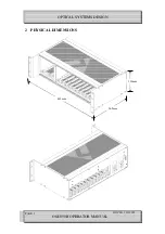
Page 5: ...OPTICAL SYSTEMS DESIGN DOC ID 10112902 OSD350B OPERATOR MANUAL PAGE 2 2 PHYSICAL DIMENSIONS 133mm 483mm 265mm...

Page 6: ...Alarm LED on the front panel of the OSD921 is green during normal operation and will be red when the operating temperature exceeds the normal operating limits of the supply Do not continue to operate...

Page 7: ...it when each of the power supplies is operational If there is a power supply failure or excessive operating temperature the alarm output is connected to ground via a relay The pin out of the 9 pin D f...

Page 8: ...tems Design Warriewood Australia or its nominated authorised representative for all repairs 5 2 1 WARRANTY REPAIRS Return shipments to OSD shall be at customer s expense and freight back to the custom...

Page 9: ...OPTICAL SYSTEMS DESIGN DOC ID 10112902 OSD350B OPERATOR MANUAL PAGE 6...

Page 10: ...OPTICAL SYSTEMS DESIGN DOC ID 10112902 OSD350B OPERATOR MANUAL PAGE 7...

Page 11: ......

Page 12: ...uko Pl Warriewood 2102 P O Box 891 Mona Vale N S W Australia 2103 Telephone 61 2 9913 8540 Facsimile 61 2 9913 8735 Email sales osd com au Web Site www osd com au OPTIC L SYSTEMS DESIGN PTY LTD A B N...

Reviews: