background image


OPTICAL SYSTEMS DESIGN 


DOC ID: 10104512 

OSD860 OPERATOR MANUAL


PAGE 8 


2.3


POWER SUPPLY CONNECTIONS 


The OSD860 card version requires DC power which is connected via a DB9 connector and supplied by 
the OSD370 or OSD350 chassis. The card should be fixed into the chassis using the captivated screws. 
The cards can be plugged in or out of the chassis with power on or off.  
 
The OSD860 module version requires external DC power and is connected to the power socket located 
at the back of the case. Power should be connected as indicated in Table 4. 
 
The 2RU rack version requires AC mains power supplied by standard IEC mains plug of 90V

AC 

to


265V

AC 

@ 20VA. Fuse: 1A Antisurge. 


TABLE 4: POWER CONNECTION 


OSD860 Version 

Specification 

Power 

Connection 

Card 

12V

DC


Supplied by OSD370 

or OSD350 chassis 

DB9 

Module 

10 to 18V

DC 

Power Pack 15VA 

2 way terminal 

connector 

2RU 

90 V

AC 

to


265 V

AC  @ 

20VA 

Mains Power 

IEC mains plug 


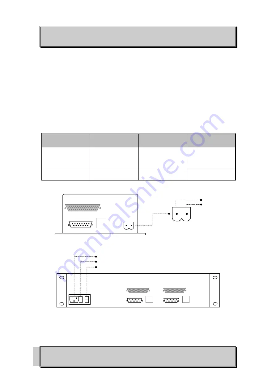
FIGURE 3: OSD860 POWER SUPPLY CONNECTIONS 


Power Connector 

Ground 
+10 to 18V

DC


IEC mains connector 
Fuse: 1A Antisurge 
On/Off Switch 


¦ 

Summary of Contents for OSD860 SERIES

Page 1: ...OPERATOR MANUAL OSD860 SERIES DIGITAL 2 4 8 CHANNEL VIDEO AUDIO DATA IP FIBER OPTIC MULTIPLEXER...

Page 2: ......

Page 3: ...4 WARRANTY 17 4 1 WARRANTY PERIOD 17 4 2 REPAIRS 17 4 2 1 WARRANTY REPAIRS 17 4 2 2 OUT OF WARRANTY REPAIRS 17 4 2 3 SITE REPAIRS 17 4 2 4 EXCLUSIONS 17 TABLE 1 PRODUCTS AND OPTIONS 4 TABLE 2 OSD860...

Page 4: ...100 Base T Ethernet connection is also a fitted option The resulting digital signals are multiplexed and transmitted as a digital bit stream through the fiber as a laser light source operating at 1310...

Page 5: ...nels which may be one way or full duplex Alternatively the user may transmit eight audio or eight extra data signals again either one way or full duplex Range of up to 120km is possible with optional...

Page 6: ...ork Management System TABLE 2 OSD860 POSSIBLE CONFIGURATIONS OPTION OSD860T OSD860R VIDEO DATA AUDIO VIDEO DATA AUDIO F Basic 4V 8V 4D 4V 8V 4D B Audio Data 4V 8V 8D 4A 4V 8V 8D 4A B Audio 4V 8V 4D 4A...

Page 7: ...BNC Standard Data Connectors Female 15 pin D connector Optional Audio Data Connector Female 44 pin high density D connector Transmitter Wavelength 1310nm or 1550nm including CWDM devices from 1470 to...

Page 8: ...designed to be mounted on an even surface and to be secured by means of M4 or smaller screws The card versions are designed to be inserted into a chassis and secured by means of captivated screws FIGU...

Page 9: ...duct may cause radio interference in which case the user may be required to take adequate measures OPTICAL OUTPUT OPERATION WARNING Laser Safety Class 1 Laser Product per IEC EN 60825 1 20011 standard...

Page 10: ...wer and is connected to the power socket located at the back of the case Power should be connected as indicated in Table 4 The 2RU rack version requires AC mains power supplied by standard IEC mains p...

Page 11: ...rear panel FIGURE 4 BASIC DATA CONNECTIONS 2 4 1 BASIC OPTION CONNECTOR TABLE 5 BASIC OPTION DB15 FEMALE CONNECTOR AND PIN ASSIGNMENTS PIN DATA CONNECTION PIN DATA CONNECTION 1 RS422 INPUT 1 RS485 INP...

Page 12: ...nes on both ends Some devices are marked opposite the RS485 standard 2 4 1 1 RS485 OPERATION The standard OSD860 is configured for RS422 operation Typically the unit will be set to RS485 2 Wire or 4 W...

Page 13: ...ombinations 4 or 8 data channels 4 or 8 audio channels 4 data and 4 audio channels The data channels are capable of accepting RS232 TTL or RS422 and RS485 Data is connected to the OSD860 via the DB44...

Page 14: ...H4 RS422 Output CH8 Audio Output CH4 RS422 Output 22 CH4 RS422 Output CH8 Audio Output CH4 RS422 Output 27 CH1 Audio Input CH1 Audio Input CH5 Data Input 28 CH1 Audio Input CH1 Audio Input CH5 Data In...

Page 15: ...witches 2 3 and 4 set the RS485 Turnaround Delay to the delay appropriate to your system Table 7 If you are not sure of the correct delay value leave all Turnaround Delay switches Off ie up All two wi...

Page 16: ...up to 8 video channels up to 16 on 2RU version The video input signal eg from camera is connected to the video input BNC connectors on the OSD860 transmitter The video output signal eg to monitor is...

Page 17: ...hat correct fiber is connected ie from OSD860T transmitter to the OSD860R receiver and vice versa ROS Received Optical Signal LED will change from Red to Green To connect composite video signals conne...

Page 18: ...of their support circuitry Some components within the unit are electrostatic sensitive and ESD precautions should be taken when performing maintenance upon the unit 3 2 EXTERNAL INSPECTION Visually c...

Page 19: ...e for all repairs 4 2 1 WARRANTY REPAIRS Return shipments to OSD shall be at customer s expense and freight back to the customer will be at OSD expense 4 2 2 OUT OF WARRANTY REPAIRS OSD reserves the r...

Page 20: ...ko Pl Warriewood 2102 P O Box 891 Mona Vale N S W Australia 2103 Telephone 61 2 9913 8540 Facsimile 61 2 9913 8735 Email osdsales osd com au Web Site www osd com au OPTIC L SYSTEMS DESIGN PTY LTD A B...

Reviews: