OPTICAL SYSTEMS DESIGN
DOC ID: 10104512
OSD860 OPERATOR MANUAL
PAGE 15
2.7
OSD860 OPERATION
If a card version is used, insert it in an appropriate slot on the OSD chassis and check that the indicators
illuminate correctly on power up. If a module version is used, connect the unit to an appropriate power
source and check that the indicators illuminate correctly on power up.
In either case take special note of the “Laser OK” indicator, it should be green. If it is red there may be
a problem with the laser device. Disconnect power and have the unit checked as soon as possible.
Connect the appropriately terminated fiber cable to the OSD860 receiver, checking that correct fiber is
connected ie. from OSD860T transmitter to the OSD860R receiver (and vice versa). "ROS” (Received
Optical Signal) LED will change from Red to Green.
To connect composite video signals, connect 75
Ω
BNC terminated coaxial cable from the camera to
the OSD860T video inputs. Connect 75
Ω
BNC terminated coaxial cable from the OSD860R video
outputs to the video monitor/switcher.
Plug the digital signal source (data) into the DB15 (or data/audio to the optional DB44) connector on
the rear of the module. Ensure that the correct signals are connected to the correct pins of Audio/Data
Input/Output connector as specified in Table 5 or Table 6.
2.7.1
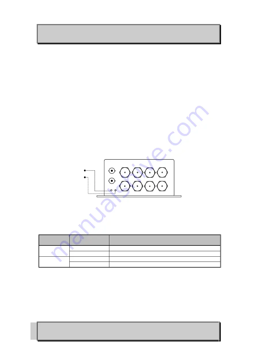
OSD860 INDICATORS
FIGURE 12: OSD860 INDICATORS
TABLE 8: OSD860 INDICATORS
INDICATOR
COLOUR
FUNCTION
ROS
Red
No or low signal detected
Green
Received optical signal OK
LD
Red
Laser faulty
Green
Laser OK
ROS
LD
Summary of Contents for OSD860 SERIES
Page 2: ......


