


Summary of Contents for CHIARO NANOINDENTER
Page 1: ...PIUMA NANOINDENTER USER MANUAL ...
Page 63: ...63 Flowchart Calibration ...
Page 65: ......
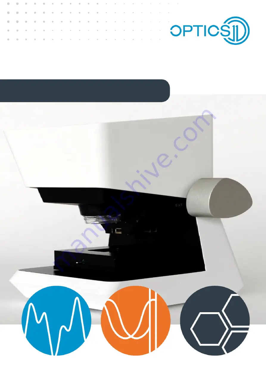
The Optics11 CHIARO NANOINDENTER is a cutting-edge, precision instrument for nanomechanical characterization. To help you make the most of its advanced features, we offer a comprehensive User Manual, available for free download from our website. Unlock the full potential of your Nanoindenter with this invaluable resource.
Page 1: ...PIUMA NANOINDENTER USER MANUAL ...
Page 63: ...63 Flowchart Calibration ...
Page 65: ......


