Page 11
Only for IS-01SMD
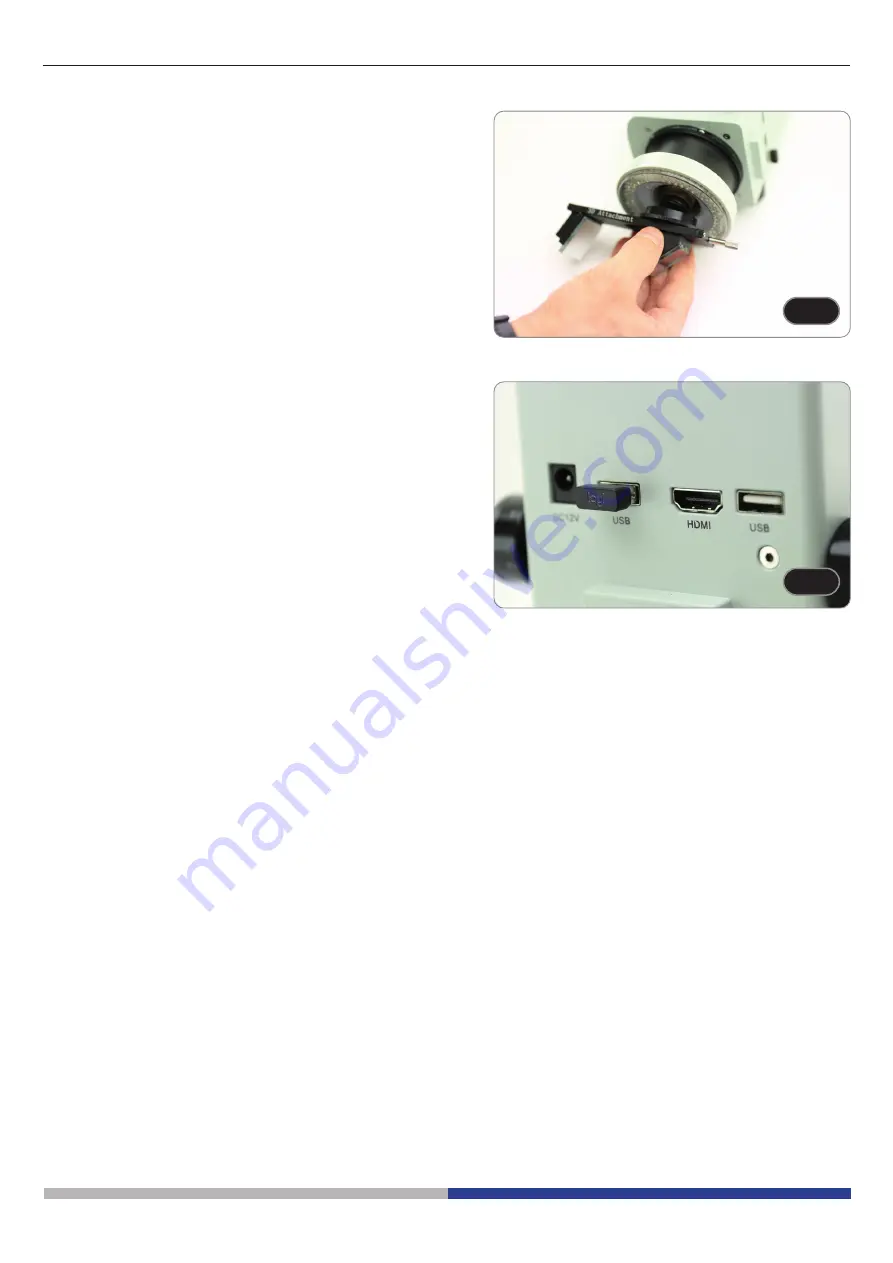
Screw the 3D attachment on the lens thread on the microscope
body. (Fig. 5)
F
Fig. 5
ig. 5
F
Fig. 6
ig. 6
5.
Connect the wireless mouse receiver in the USB port
Ⓐ
, the
HDMI cable in the port
Ⓑ
and the power supply jack in the
connector
Ⓒ
. (Fig. 6)
6.
Connect a USB flash disk into the port
Ⓓ
.
• There is no ON-OFF switch on the microscope: when
the power supply is connected, the system starts up
automatically and begins projecting images onto the
monitor.
• It takes approximately 10-15 seconds for the system to
start up before the image is displayed.
Ⓒ
Ⓑ
Ⓐ
Ⓓ
Summary of Contents for INSPECTION SYSTEMS Series
Page 1: ...Ver 2 1 2021 INSTRUCTION MANUAL INSPECTION SYSTEMS Series Model IS 01 IS 01SMD...
Page 14: ...Page 14 10 Use of the software 10 1 Menu Interface a Control...
Page 15: ...Page 15 b Measurement...
Page 33: ...Modello IS 01 IS 01SMD Serie INSPECTION SYSTEMS MANUALE DI ISTRUZIONI Ver 2 1 2021...
Page 46: ...Pagina 46 10 Uso del software 10 1 Interfaccia del Menu a Controllo...
Page 47: ...Pagina 47 b Misurazioni...
Page 65: ...Ver 2 1 2021 MANUAL DE INSTRUCCIONES Serie INSPECTION SYSTEMS Modelo IS 01 IS 01SMD...
Page 78: ...P gina 78 10 Uso del software 10 1 Interfaz del men a Control...
Page 79: ...P gina 79 b Medici n...
Page 97: ...Ver 2 1 2021 MANUEL D UTILISATION S rie INSPECTION SYSTEMS Mod le IS 01 IS 01SMD...
Page 110: ...Page 110 10 Utilisation du logiciel 10 1 Interface du menu a Contr le...
Page 111: ...Page 111 b Mesures...
Page 129: ...Ver 2 1 2021 BEDIENUNGSANLEITUNG INSPECTION SYSTEMS Series Modell IS 01 IS 01SMD...
Page 142: ...Seite 142 10 Verwendung der Software 10 1 Men Schnittstelle a Kontrolle...
Page 143: ...Seite 143 b Messung...
Page 161: ...Ver 2 1 2021 MANUAL DE INSTRU ES S rie INSPECTION SYSTEMS Modelo IS 01 IS 01SMD...
Page 174: ...P gina 174 10 Uso do software 10 1 Interface do menu a Controlo...
Page 175: ...P gina 175 b Medi o...


