5
Chapter 3
Status Indicators and Back Panel Connections
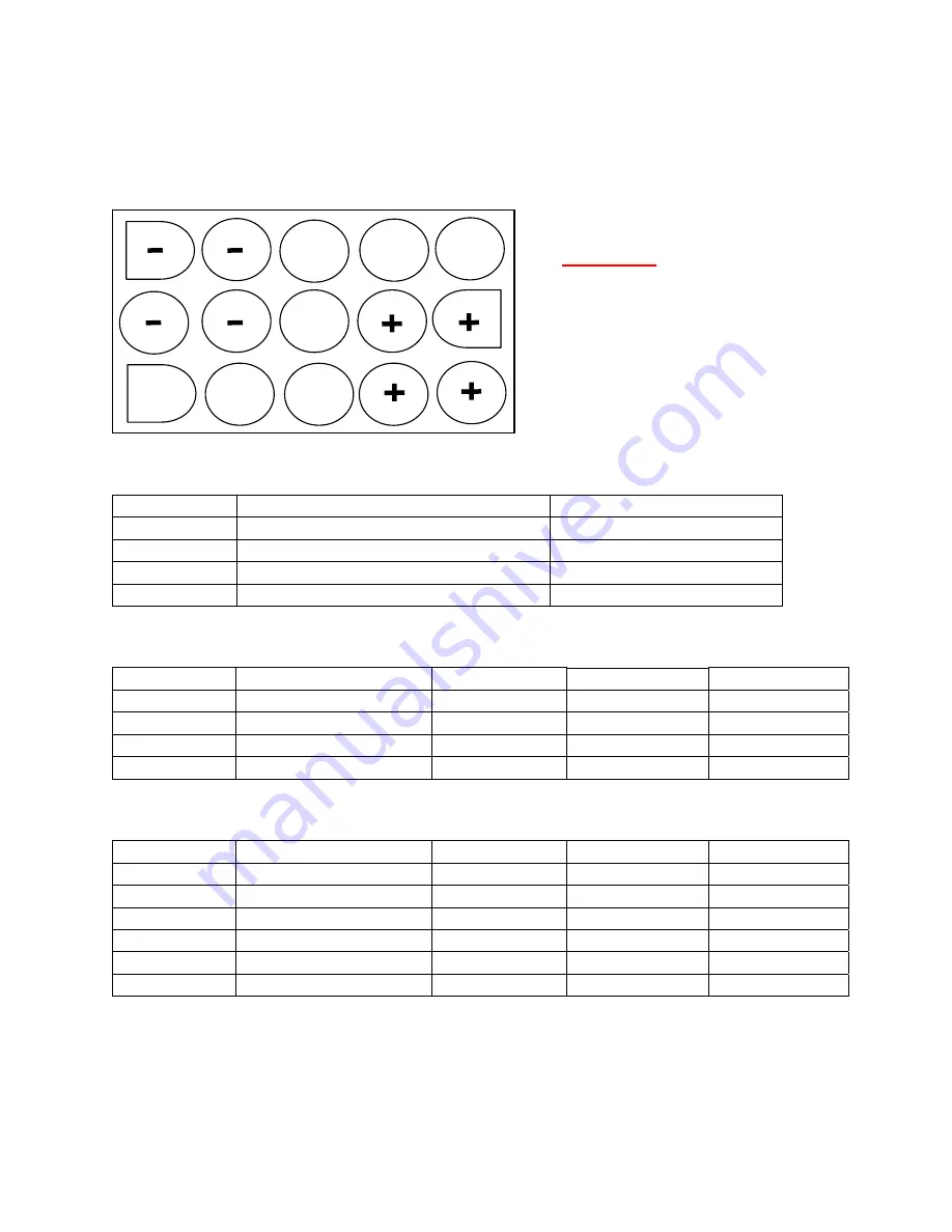
3.1 Back Panel DC Power Connector
3.2 Front Panel Status Indicators
LED
Description (When Lit)
Labeled Indicators
Solid Green
Power Supply 1 Activated
Power 1
Solid Red
Power Supply Failure
PS 1 Alarm
Solid Green
Power Supply 2 Activated
Power 2
Solid Red
Power Supply Failure
PS 2 Alarm
3.3 Remote Management DB25 Pin Out for OPR200-05S
Pin Numbers
Description
I/O Direction
Logic High = 1
Logic Low = 0
Pin # 3
Power Supply Alarm
+RS485Output
Alarm No
Alarm
Pin # 16
Power Supply Alarm
–RS485 Output
No Alarm
Alarm
Pin # 1
Frame Ground
Output
NA
NA
Pin # 7
Signal Ground
1
Output
NA
NA
3.4 Remote Management DB25 Pin Out for OPR200-05R
Pin Numbers
Description
I/O Direction
Logic High = 1
Logic Low = 0
Pin # 3
Power Supply 1 Alarm +RS485Output
Alarm No
Alarm
Pin # 16
Power Supply 1 Alarm –RS485 Output
No Alarm
Alarm
Pin # 9
Power Supply 2 Alarm –RS485Output
No Alarm
Alarm
Pin # 17
Power Supply 2 Alarm +RS485 Output
Alarm No
Alarm
Pin # 1
Frame Ground
Output
NA
NA
Pin # 7
Signal Ground
1
Output
NA
NA
Note 1: For proper remote management interface functionality. It is importance to connect the signal
ground properly and securely.
+ Indicates 5 Volt DC
– Indicates Ground Lin
e
WARNING: Observe
polarity when making
connection to the rear of
Model OPR200-05S /
Model OPR200-05R


