6
Chapter 3
Status Indicators and Back Panel Connections
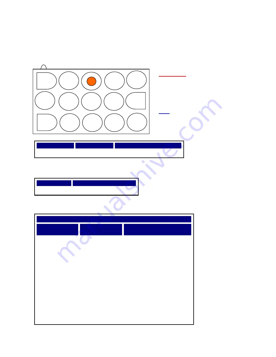
3.1 Back Panel DC Power Connector for RPS
Pin Numbers
Signal Name
Function
Pin 7
RPS Present
Logic Low = RPS Present
3.2 Front Panel Status Indicators
LED
Description
Solid Green
DC Power Supply Status
3.3 Compatible NETGEAR® Switch Model Number Table
Compatible NETGEAR® Switch Model Number Table
NETGEAR®
Switch Model
Optimal Power
®
RPS Models
Optimal Power
®
DC Cable
GSM7224-200
RPS5412
RPSC5412
GSM7248-200
RPS5412
RPSC5412
GSM7228PS
RPS5412
*
RPSC5412
GSM7252PS
RPS5412
*
RPSC5412
GSM7328S-200
RPS5412
RPSC5412
GSM7352S-200
RPS5412
RPSC5412
GSM7328FS
RPS5412
RPSC5412
GSM7212F
RPS5412
RPSC5412
GSM7212P
RPS5412
RPSC5412
GSM7224P
RPS5412
RPSC5412
* NOTE
The Model RPS5412 only provides up to 300W for POE application. If POE
devices connected to the switch system need more than 300W, then this device is not
recommended.
–52V
RTN
–52V
–52V
7
–52V
RTN
GND
GND
GND
+12V
+12V
+12V
WARNING:
Observe polarity when making
connection to the rear of the RPS
Model RPS5412
Note: Refer to next 2 pages for DC
cable connections


