Appendix
Version 1.2.3 - 2021-11-02
97
Translation of original instruction
S275N | S275NV
EN
S275
N
_S275
NV_G
B_8.
fm
7
Appendix
7.1
Copyright
This document is protected by copyright. All derived rights are reserved, especially those of
translation, re-printing, use of figures, broadcast, reproduction by photo-mechanical or similar
means and recording in data processing systems, either partial or total.
Subject to technical changes without notice.
7.2
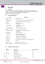
Terminology/Glossary
7.3
Change information manual
Term
Explanation
Workpiece
•
Material to be cut
Blade guide pulley
•
Pulley through which the saw blade passes in the saw arch
Saw arch
•
Housing with protective cover for the saw blade
Material stop
•
Position for multiple cuts
•
Sawing stop
Hydraulic cylinder
•
Hydraulic lowering cylinder
•
Hydraulic feed
Feed regulation valve
•
Valve on the hydraulic cylinder
Protective cover saw arch
•
Cover on the rear of the saw arch
Blade guide bearings
•
Rollers between which the saw blade passes
•
Guide bearing
Saw belt guide
•
Blade guide bearings
Saw blade brush
•
Device for scraping off impurities
•
Saw blade cleaning brush
Clamping jaw
•
Strip terminal on the machine vice
Machine vice
•
Clamping device for the workpiece
Worm gear
•
Reduction gear from drive motor to the belt guidance rollers
Drive motor
•
Engine
Emergency stop
Stops the operation of a machine.
Emergency switching off
Interrupts the power supply of the machine.
Chapter
Short note
new version no.
1.4.1
Avoiding misuse
1.0.1
CE
declaration
1.0.1
CE conformity
notified body, SGS
1.0.2
1.4.1
EMC, class C2 to class C3
1.0.3
EC
New type C standard
1.0.4
3 , parts
modificated substructure for SE1 levelling discs
1.1.0

