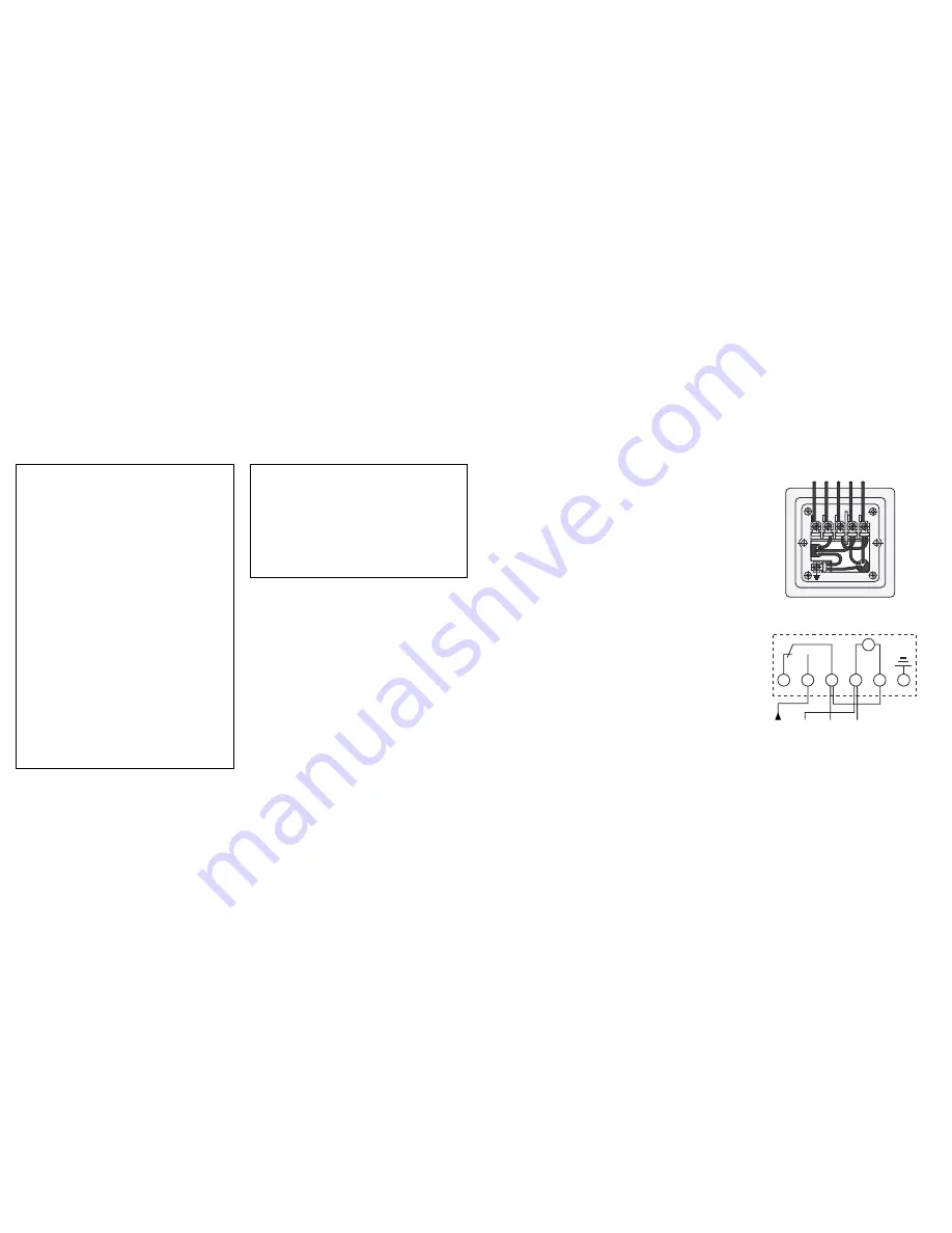
screws, in accordance with circuit diagram
label
beneath terminals.
Note:
Do not connect unprepared
stranded wires. Use ferrules supplied
to crimp stranded wire terminations.
3. Fix backplate to socket box.
4. Connect wiring in accordance with wiring
diagram.
5. Fit cover over module and reassemble to
backplate. Ensuring fixed blue wires are
stowed neatly without being trapped.
6. Re-fit and tighten two screws.
7. Switch on mains.
2.
●
The timer should not be mounted on an
unearthed metal or metallised surface.
●
If the timer is to be connected to an
appliance that is required to be earthed the
supply earthing conductor and the
appliance earthing conductor should be
terminated together in the earth terminal
provided within the timer.
1.
Installation procedure
1. Switch the supply off at the mains. Means
of disconnection from the supply having at
least 3 mm contact separation in all poles
must be incorporated in the fixed wiring
mains supply.
2. Unscrew the two screws located top right
and bottom left of front module cover;
remove cover and gently pull module from
backplate. Do not put undue stress on, ‘or’
interfere with fixed connecting wires. Bare
wires
back for 6 mm (1/4 inch) maximum;
insert into terminals and secure with the
Please read the instructions fully
before attempting installation.
IMPORTANT
Installation must be carried out in
accordance with the current edition of
the I.E.E. Wiring Regulations. It is
recommended that installation is
undertaken only by a qualified
electrician.
●
Timer must not be mounted on a
flammable surface.
●
Ensure that the timer does not come
into contact with any combustible
materials such as towels or bedding.
●
Ensure at least a 300 mm air space is
allowed around the timer.
OP-SBWF01 Installation Instructions
Backplate wiring: Example (230V AC 50-60Hz)
Wiring diagram (230V AC 50-60Hz)
M
~
1
2
3
4
5
5
4
3
2
1
E
L
N
L
N
to appliance
mains supply


