background image

OPTIMUM

M A S C H I N E N   -   G E R M A N Y

Assembly

Version 1.0  dated 2015-06-18

Page 17

Original operating instructions

S275N | S275NV

GB

3

Assembly

3.1

Unpacking the machine

Transport the metal belt saw in its packing crate to a place near its final installation location with
a forklift before unpacking it. 
If the packaging shows signs of possible transport damage, take the necessary precautions not
to damage the machine when unpacking. If any damage is discovered, the carrier and/or ship-
per must immediately be notified of this fact to establish any claim which might arise.
Inspect the machine completely and carefully, making sure that all materials, such as shipping
documents, manuals and accessories supplied with the machine have been received.
Compare the delivery volume with the delivery note.

3.2

Transport

WARNING!

Severe or fatal injuries may occur if parts of the machine tumble or fall down from the
forklift truck or from the transport vehicle. Follow the instructions and information on
the transport box. Note the total weight of the metal belt saw. Use only transport and
load suspension devices that can hold the total weight of the metal belt saw. 

WARNING!

The use of unstable lifting and load suspension equipment that might break under load
can cause severe injuries or even death. Check that the lifting and load suspension gear
has sufficient load capacity and that it is in perfect condition. Fasten the loads properly.
Never walk under suspended loads!

Summary of Contents for OptiSaw S 275N

Page 1: ...GB OPTIMUM M A S C H I N E N G E R M A N Y Operating Manual Version 1 0 Metal belt saw Item no 3300260 Item no 3300265 ...

Page 2: ...pment 12 1 11 Safety during operation 13 1 12 Safety during maintenance 13 1 12 1 Disconnecting and securing the metal belt saw 13 1 12 2 Using lifting equipment 13 1 12 3 Mechanical maintenance work 13 1 13 Accident report 14 1 14 Electronics 14 1 15 Inspection deadlines 14 2 Technical data 2 1 Type plate 15 2 2 Emissions 16 3 Assembly 3 1 Unpacking the machine 17 3 2 Transport 17 3 3 Dimensions ...

Page 3: ...S275N S275NV 6 1 Bandsäge 1 3 Band saw 1 3 39 6 2 Bandsäge 2 3 Band saw 2 3 40 6 3 Bandsäge 3 3 Band saw 3 3 41 6 4 Getriebe Gear box 42 6 5 Maschinenunterbau Substructure 43 6 6 Schaltkasten Electrical box S275N 44 6 7 Schaltkasten Electrical box S275NV 45 6 8 Schaltplan Wiring diagram 400V S275N 46 6 9 Schaltplan Wiring diagram S275NV 47 6 9 1 Ersatzteilliste Spare parts list S275N S275NV 48 7 M...

Page 4: ...vice life In the paragraph Maintenance all maintenance works and functional tests are described which the operator must perform in regular intervals The illustration and information included in the present manual can possibly deviate from the current state of construction of your machine Being the manufacturer we are continuously seeking for improvements and renewal of the products Therefore chang...

Page 5: ...signs as well as the warning notes on the metal belt saw European standards must be kept during installation operation maintenance and repair of the circular metal saw If European standards have not yet been incorporated in the national legislation of the country of destination the specific applicable regulations of each country must be observed If required it is necessary to take the correspondin...

Page 6: ...anger that can cause serious injury or death CAUTION A danger or unsafe procedure that can cause personal injury or damage to property ATTENTION Situation that could cause damage to the machine and product and other types of damage No risk of injury to people INFORMATION Practical tips and other important or useful information and notes No dangerous or harmful consequences for people or objects In...

Page 7: ...d ance with intended use If the metal belt saw is used in any way other than described above modified without authoriza tion of Optimum Maschinen Germany GmbH then the metal belt saw is being used improperly We will not be held liable for any damages resulting from any operation which is not in accord ance with the intended use We expressly point out that the guarantee or CE conformity will expire...

Page 8: ... vibration Long workpieces must be propped up Use a suitable support 1 5 Possible dangers caused by the metal belt saw The metal belt saw has been tested for operational safety The construction and type are state of the art Nevertheless there is a residual risk as the metal belt saw operates with electrical voltage and currents an revolting saw band We have used construction resources and safety t...

Page 9: ... pany Qualified electrician With professional training knowledge and experience as well as knowledge of respective standards and regulations qualified electricians are able to perform work on the electrical sys tem and recognise and avoid any possible dangers Qualified electricians have been specially trained for the working environment in which they are working and know the relevant standards and...

Page 10: ...electrician Before starting work on electrical parts or operating agents following measures are to be per formed in the following order disconnect all poles secure against restarting check that there is no voltage 1 7 Safety measures during operation CAUTION Danger due to inhaling dust and mist that is hazardous to health Dependent on the material which need to be processed and the used auxiliarie...

Page 11: ...d the rotating saw belt INFORMATION The metal belt saw only switches on when the protective cover is being closed WARNING Danger of injury The teeth of the saw belt are sharp Take great care when opening the protective cover to change the saw blade Close and mount all protective covers before restarting the metal belt saw 1 8 3 Saw belt guide Refit the protective covers after each exchange of the ...

Page 12: ...n your personal protective equipment after each use regularly once a week Personal protective equipment for special works Protect your face and your eyes Wear a safety helmet with facial protection when performing work where your face and eyes are exposed to hazards Wear protective gloves when handling pieces with sharp edges Wear safety shoes when you assemble disassemble or transport heavy compo...

Page 13: ...d if necessary a hairnet Inform the supervisor about all hazards or faults 1 12 Safety during maintenance Report and documentany changes Inform the operators in good time of any maintenance and repair works Report all safety relevant changes and performance details of the metal belt saw Any changes must be documented the operating instructions updated and machine operators instructed accordingly 1...

Page 14: ...erating equipment inspection The operator of the machine must ensure that the electrical systems and operating equipment are inspected with regards to their proper condition namely by a qualified electrician or under the supervision and direction of a qualified electrician prior to initial commissioning and after modifications or repairs prior to recommissioning and at certain intervals The deadli...

Page 15: ...gle adjustment using the rotating saw arch 0 60 Saw belt guide Saw belt guides supported on ball bearings Raising the saw arch manually Feed continuously adjustable Saw band tension Manually using the hand wheel Dimensions S275N S275NV Weight of the metal belt saw kg 185 Dimensions of saw blade mm 2480 x 27 x 0 9 Dimensions S275N S275NV on page 18 Speed of saw belt S275N S275NV m min 45 90 20 90 T...

Page 16: ... it is not possible to use it reliably to determine if further precaution measures are required or not The following factors influence the actual degree of the noise exposure of the operator Characteristics of the working area e g size or damping behaviour other noise sources e g the number of machines other processes taking place in proximity and the period of time during which the operator is ex...

Page 17: ... that all materials such as shipping documents manuals and accessories supplied with the machine have been received Compare the delivery volume with the delivery note 3 2 Transport WARNING Severe or fatal injuries may occur if parts of the machine tumble or fall down from the forklift truck or from the transport vehicle Follow the instructions and information on the transport box Note the total we...

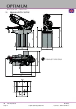
Page 18: ... M A N Y Assembly Version 1 0 dated 2015 06 18 Page 18 Original operating instructions S275N S275NV GB 3 3 Dimensions S275N S275NV A A A A 685 945 1400 985 510 550 815 1700 230 12 510 550 482 940 225 Schwerpunkt Centre of gravity 910 ...

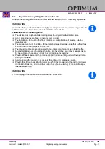
Page 19: ...lso at a distance of presses planing machines etc The substructure must be suitable for the metal belt saw Also make sure that the floor has sufficient load bearing capacity and is level The ground must be prepared in a way that potential coolants cannot penetrate the floor Any parts sticking out such as stops handles etc have to be secured by measures taken by the customer if necessary in order t...

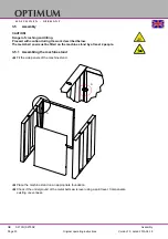
Page 20: ... tilting Proceed with caution during the work described below The metal belt saw must be fitted on the machine stand by at least 2 people 3 5 1 Assembling the machine stand Fit the side panels of the machine stand Place the machine stand on an appropriate foundation Check if the underground of the metal belt saw is level using a spirit level Compensate existing unevenness A A ...

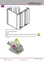
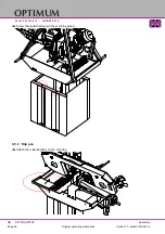
Page 21: ...275NV GB Fasten the machine stand to the ground Place the metal belt saw on the machine stand 3 5 2 Load suspension point DANGER Danger of crushing and overturning The metal belt saw must be installed by several per sons Insert steel rods through the holes in the chip tray Attach lifting slings on both sides of the steel rods ...

Page 22: ...I N E N G E R M A N Y Assembly Version 1 0 dated 2015 06 18 Page 22 Original operating instructions S275N S275NV GB Screw the metal belt saw to the machine stand 3 5 3 Drip pan Attach the collecting tray on the chip tray ...

Page 23: ... Install the connection cable of the machine in such a way that people will not stumble over it Connect the three phase electric cable to the machine Check the fusing fuse of your electrical supply Fusing 10A 16A ATTENTION Ensure that all 3 phases L1 L2 L3 and the ground wire are connected correctly The neutral conductor N of its power supply is not connected If the machine is already equipped wit...

Page 24: ...N Danger of cutting perform the works described hereunder with care Use the prescribed protective equipment Inspecting the belt guide pulleys Check if the saw blade is mounted correctly onto the belt guide pulleys Check that the saw belt fits snugly inside the guide bearings Check the tension of the saw belt Proper blade tension is reached when the saw band has been stretched to the green mark on ...

Page 25: ...s S275N S275NV GB 4 Operation 4 1 Control and indicating elements Pos Designation Pos Designation 1 Handle 2 Saw band tension 3 Saw arch 4 Adjustable saw belt and coolant hose guide 5 Quick action vice 6 Clamping lever angular adjustment saw arch 7 Control panel 8 Feed regulation valve 9 Sawing stop 3 7 1 2 4 5 6 8 9 ...

Page 26: ... on page 13 4 3 Inserting the workpiece Raise the saw arch Close the stop cock to secure the arch in a given position Img 4 1 Hydraulic feed Place the piece to be cut in the workholder vice CAUTION Danger of tilting Support long work pieces before pushing the piece to be cut into the work holder vice The saw arch can be regulated with continuous advance for angular cuts Position the clamp approxim...

Page 27: ...ear down 4 6 Switching on the machine Check that the EMERGENCY Stop switch is not pressed or unlocked Turn the EMER GENCY Stop switch to the right in order to unlock it Actuate the push button ON 4 7 Switching off the machine Actuate the push button OFF Disconnect during an extended standstill the power plug CAUTION The emergency stop switch may only be activated in an emergency A normal shut down...

Page 28: ... refer in the specialized trade Make sure that the cooling agent is properly retrieved Respect the environment when disposing of lubricants and coolants Follow the manufacturer s disposal instructions Switch on the cooling units by pressing the switch 4 11 Starting the metal belt saw Start the metal belt saw by pressing the green button Material m min Feed motion per tooth mm Material m min Feed m...

Page 29: ...ulation valve Open the stop cock Img 4 5 Hydraulic feed The belt saw automatically switch off when you reach your end position Follow the same steps in reverse order to remove the work piece from the vice EMPIRICAL RULE The finer the tooth spacing and or the thinner or smaller the work piece the lower the feed should be 4 13 Cutting area Possible cutting areas S275N and S275NV Feed regulation valv...

Page 30: ...l systems and operating materials may only be installed modified and repaired by a trained electrician or supervised and under the control of a trained electrician and must comply with electrotechnical regulations WARNING Do not climb onto or into the machine while working 5 1 1 Preparation WARNING Only work on the metal belt saw when the mains plug is disconnected Attach a warning sign 5 1 2 Rest...

Page 31: ...up to 600 kgs cm2 for standard metal saw belts 650 kgs cm2 up to 750 kgs cm2 for bi metal saw belts Img 5 1 saw belt tension INFORMATION Do not strain the saw belt more than necessary The saw belt could be overstretched and become warped As required and after changing the saw belt Saw arch Adjusting the saw belt tension Adjusting the posi tion of the saw belt on the saw belt roll ers The saw belt ...

Page 32: ...rch on the weighing machine should come to 15 16 kg If necessary correct the value by changing the posi tion of the spring using the adjusting screw Img 5 3 Saw arch pressure If the metal belt saw and the cool ing pump continue to oper ate after the saw ing process is complete If the metal belt saw and the cool ing pump switch off before sawing is termi nated Adjusting the end stop switch Turn the...

Page 33: ...o the oil in the helical gear before the machine is first used This reduces wear in the flanks of the teeth and increases the useful service life of the gear As required Machine vice Spindle Lubricate the spindle of the work holder vice Annually Drive Oil change Unscrew the oil bleed screw at the bottom of the heli cal gear Use an adequate vessel with enough capacity to collect the oil Open the fi...

Page 34: ...the saw belt by turning the hand wheel anti clockwise Carefully remove the old saw belt Fit the new saw blade by inserting it first into the saw belt guide Check the running direction and toothing Direc tion of the saw teeth on page 24 Place the saw belt on the two pulleys so that it is as close as possible to the casing of the saw arch Tighten the saw belt Run a check as described in First commis...

Page 35: ... Optionally the Stürmer Maschinen GmbH Dr Robert Pfleger Str 26 D 96103 Hallstadt can provide a customer service technician however the request for a customer service techni cian can only be made via your specialist dealer If repairs are performed by other qualified technical personnel they must follow the instructions in this operation manual Optimum Maschinen Germany GmbH accepts no liability no...

Page 36: ... 6 ml there is an increase in nitrite content to more than 20 ppm mg 1 or nitrate content to more than 50 ppm mg 1 there is an increase in the N nitrosodiethanolamine NDELA to more than 5 ppm mg a CAUTION Comply with the manufacturer s specifications for mixture ratios hazardous substances e g system cleaners including their permissible minimum use times CAUTION Since the cooling lubricant escapes...

Page 37: ...ased on initial filing Measures in accordance manufacturer s rec ommendations 1 0 based on initial filing Replace cooling lubricant clean cooling lubri cant circulation system Usage concentration Manual refractometer weekly 1 Method results in incorrect values with tramp oil content Base reserve Acid titration in accordance with Manufacturer s recommenda tion as required Method is independent of t...

Page 38: ...OPTIMUM M A S C H I N E N G E R M A N Y Version 1 0 vom 2015 06 18 Seite 38 Original operating instructions Kühlschmiermittel DE ...

Page 39: ...9 Originalbetriebsanleitung S275N S275NV DE GB 6 Ersatzteile Spare parts S275N S275NV 6 1 Bandsäge 1 3 Band saw 1 3 Abb 6 1 Bandsäge 1 3 Band saw 1 3 141 27 47 24 105 104 49 49 44 46 130 78 78 98 86 99 84 54 53 42 137 1 137 137 138 10 7 91 159 160 161 162 163 164 158 166 167 168 169 170 171 172 173 207 ...

Page 40: ... Version 1 0 2015 06 18 40 Originalbetriebsanleitung S275N S275NV DE GB 6 2 Bandsäge 2 3 Band saw 2 3 Abb 6 2 Bandsäge 2 3 Band saw 2 3 76 55 56 78 99 7 115 136 78 98 71 92 169 168 55 1 167 174 50 175 176 177 178 161 179 180 164 154 154 180 152 152 64 211 212 213 214 215 216 77 ...

Page 41: ... 41 Originalbetriebsanleitung S275N S275NV DE GB 6 3 Bandsäge 3 3 Band saw 3 3 Abb 6 3 Bandsäge 3 3 Band saw 3 3 63 62 61 93 59 57 60 45 9 8 6 67 19 18 20 64 30 32 28 28 28 31 121 120 122 122 123 126 127 125 124 65 126 148 149 150 151 152 151 153 217 154 156 157 151 158 147 142 146 144 145 143 210 66 ...

Page 42: ...re parts S275N S275NV Version 1 0 2015 06 18 42 Originalbetriebsanleitung S275N S275NV DE GB 6 4 Getriebe Gear box Abb 6 4 Getriebe Gear box 131 132 36 35 2 35 1 35 26 22 34 23 181 182 183 184 185 186 187 188 188 189 190 191 192 193 194 195 195 196 197 174 ...

Page 43: ...e parts S275N S275NV Version 1 0 2015 06 18 43 Originalbetriebsanleitung S275N S275NV DE GB 6 5 Maschinenunterbau Substructure Abb 6 5 Maschinenunterbau Machine substructure 11 106 16 80 17 4 2 198 200 154 180 201 155 159 201 202 155 203 204 203 204 196 134 ...

Page 44: ...A N Y Ersatzteile Spare parts S275N S275NV Version 1 0 2015 06 18 44 Originalbetriebsanleitung S275N S275NV DE GB 6 6 Schaltkasten Electrical box S275N Abb 6 6 Schaltkasten Electrical box 114 118 119 110 1A1 111 1S2 1S1 1S7 1S9 1S3 206 ...

Page 45: ...N Y Ersatzteile Spare parts S275N S275NV Version 1 0 2015 06 18 45 Originalbetriebsanleitung S275N S275NV DE GB 6 7 Schaltkasten Electrical box S275NV Abb 6 7 Schaltkasten Electrical box 114 118 119 110 111 1S2 1S1 1S7 1S3 1A1 1R8 218 206 ...

Page 46: ... C H I N E N G E R M A N Y Ersatzteile Spare parts S275N S275NV Version 1 0 2015 06 18 46 Originalbetriebsanleitung S275N S275NV DE GB 6 8 Schaltplan Wiring diagram 400V S275N Abb 6 8 Schaltplan Wiring diagram 400V ...

Page 47: ...S C H I N E N G E R M A N Y Ersatzteile Spare parts S275N S275NV Version 1 0 2015 06 18 47 Originalbetriebsanleitung S275N S275NV DE GB 6 9 Schaltplan Wiring diagram S275NV Abb 6 9 Schaltplan Wiring diagram S275NV ...

Page 48: ...0330027536 36 Motor Motor 1 S275NV 0330027836 42 Gewindestange Threaded rod 1 0330027542 44 Handradgriff Hand wheel grip 2 0330021044 45 Innensechskantschraube Socket head screw 1 GB70 85 M5x16 0330021045 46 Nabe Hub 1 0330021046 47 Bandführungsrolle Un driven belt guide roller 1 0330027547 49 Lager Bearing 2 6205 2Z 0406205 2R 50 SägebandHSS Bi Metall Saw belt 1 10 14 ZPZ 3357525 50 SägebandHSS B...

Page 49: ... A 1 03300210143 144 Stange B Rod B 1 03300210144 145 Innensechskantschraube Socket head screw 2 GB70 75 M8x25 146 Sechskantmutter Hexagonal nut 2 ISO 4031 M8 147 Sechskantmutter Hexagonal nut 1 ISO 4031 M12 148 Scheibe Washer 1 149 Sechskantschraube Counter sunk screw 1 ISO 4014 M12x65 150 Sechskantschraube Counter sunk screw 1 ISO 4014 M12x40 151 Sechskantmutter Hexagonal nut 2 ISO 4032 M12 152 ...

Page 50: ...eibe Washer 1 03300210217 218 Knopf Knob 1 03300278218 1M1 Sägemotor Saw motor 1 S275N 1M1 1 Antriebsmotor Drive motor 1 S275NV 0330027836 1M2 Kühlmittelpumpe Cooling pump 1 S275N 1M1 2 Motor kühlmittelpumpe Coolant pump motor 1 S275NV 0330014555 1S1 Not Halt Pilzkopfschalter EMERGENCY button 1 S275N 0322793 1S2 Schalter AUS Switch OFF 1 S275N 0322790 1S3 Schalter EIN Switch ON 1 S275N 0322782 1S3...

Page 51: ...al An incorrect tooth spacing causes breakage of teeth the broken tooth in the workpiece blunts the other teeth Missing cooling Cutting speed too high Feed too high Saw belt of higher quality bimetallic blade Select correct tooth pitch Use coolant equipment Reduce cutting speed Reduce feed Breakage of tooth The chip space in the saw belt is overcharged tooth pitch incorrect Use saw belt with a dif...

Page 52: ... in the saw arch Saw arch Housing with protective cover for the saw blade Material stop Position for multiple cuts Sawing stop Hydraulic cylinder Hydraulic lowering cylinder Hydraulic feed Feed regulation valve Valve on the hydraulic cylinder Protective cover saw arch Cover on the rear of the saw arch Blade guide bearings Rollers between which the saw blade passes Guide bearing Saw belt guide Blad...

Page 53: ...liability and warranty claims Using the product beyond the technical options and proper use in particular due to over straining of the machine Any defects arising by one s own fault due to faulty operations or if the operating manual is disregarded Inattentive or incorrect handling and use of improper equipment Unauthorized modifications and repairs Insufficient installation and safeguarding of th...

Page 54: ...l conditions than those specified here 8 5 Advice for disposal Options of re use Please dispose of your machine in an environmentally friendly way not by disposing of the waste not in the environment but by acting in a professional way Please neither throw away the packaging nor the used machine later on but dispose of them according to the guidelines established by your city council municipality ...

Page 55: ... Disposing of the old device INFORMATION Please take care in your interest and in the interest of the environment that all component parts of the machine are only disposed of in the intended and admitted way Please note that the electrical devices comprise a variety of reusable materials as well as envi ronmentally hazardous components Please ensure that these components are disposed of separately...

Page 56: ...king indicates that the product must not be handled as common household waste but that is needs to be disposed of at a central collection point for recycling Your contribution to the correct disposal of this product will protect the environment and the public health Incorrect disposal constitutes a risk to the environment and public health Recycling of material will help reduce the consumption of ...

Page 57: ...U Directives have been applied EMC Directive 2014 30 EC Low Voltage Directive 2014 35 EC The safety objective meet the requirement of EC Directive 2006 42 EC The following harmonized standards were applied EN 13898 2003 A1 2009 Machine tools Safety Sawing machines for cold metal EN 50581 2012 Technical documentation for the assessment of electrical and electronic products with respect to the restr...

Page 58: ...Directive 2014 30 EC Low Voltage Directive 2014 35 EC The safety objective meet the requirement of EC Directive 2006 42 EC The following harmonized standards were applied EN 13898 2003 A1 2009 Machine tools Safety Sawing machines for cold metal EN 55011 Industrial scientific and medical equipment Radio frequency disturbance characteristics Lim its and methods of measurement EN 50581 2012 Technical...

Page 59: ...stem safety 14 Emergency stop condition reset 27 Environmental conditions 16 H Hazards Classification 6 I Intended use 6 M Malfunctions metal belt saw 51 Misuse 8 O Obligations of the operating company 9 of the operator 10 Operating material 15 Operation 25 P Protective equipment 12 Q Qualification of personnel Safety 9 S Safety devices 10 during maintenance 13 during operation 13 instructions 6 S...

Page 60: ...OPTIMUM M A S C H I N E N G E R M A N Y Version 1 0 dated 2015 06 18 Page 60 Original operating instructions S275N S275NV GB ...

Reviews: