OPTIMUM
M A S C H I N E N - G E R M A N Y
Version 1.0.1 dated 2018-01-31
Page 37
Translation of the original instructions
TM4010 | TM4010D
GB
T
M
4010_
T
M
4010D_G
B_4
.f
m
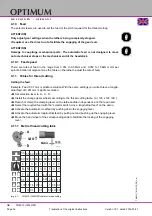
Adjusting threads
Example: Thread pitch 1.75 mm per revolution
Set selection lever to A - C - 4 - R
Install the change gears wheels according to the thread cutting table. [ a / 120 x 120 / b ]
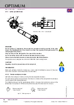
4.11.2 Exchange, change of position of the change gears
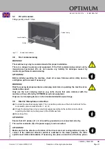
The change gears for the feed are mounted to a quadrant respectively directly on the lead
screw and feed gear.
Always disconnect the main plug
of the lathe and secure the main
switch by a padlock, against
unauthorized or accidental acti-
vation.
Open the protective cover of the
change gears.
Loosen the clamping screw on
the quadrant.
Slew the quadrant up.
Mount and position the change
gears as indicated on the table.
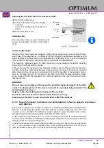
Img.4-2:
Change gears
Example:
Loosen the screws of the change
wheel
b
and the nut on the stay
rod of the intermediate wheels.
Replace the change wheel
b
according to the change wheel
table.
Adjust the intermediate wheels in
the long hole until the toothed
wheels are engaging.
Position the quadrant in a way
that the toothed wheels are
cammed in.
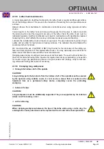
Img.4-3:
Change gears
Turn the change wheel b by 180° for inch threads in order to achieve the pace with the
intermediate wheel 127 teeth.
INFORMATION
Adjust the clearance of the tooth profile with the help of a piece of paper (80g/m
2
). Clamp the
paper as a spacing between the tooth profiles of the toothed wheels.
Locking screw
Locking screw
Intermediate
wheels
127 teeth
120 teeth
Nut
Change gear b
Mounting bolt

