background image

18

CONNECTING SPEAKERS

PREPARING THE 
SPEAKER WIRES

Caution: You must connect a sepa-
rate wire to each speaker terminal as
described in the following procedures.
Do not use a common wire or chassis
ground for any speaker connection.

Notes: 

• We recommend you use 16- or

18-gauge marked or color-coded
wires to help you correctly con-
nect the speakers to your ampli-
fier.

• Color-coded wires have a stripe

running down one of the conduc-
tors or different colored insulation
for each conductor. Your local
RadioShack store has a wide
selection of speaker wire to
choose from.

• For the maximum bass response

and the best overall performance,
keep your speakers properly
phased (c to + and – to –).

1. With the speakers placed in their

approximate locations, run one
speaker wire from each speaker
to the amplifier. 

2. Separate each speaker wire’s two

conductors at both ends for a
length of about 4 inches.

3. Strip the insulation from the ends

of each conductor to expose 

1

/

4

inch of wire. (Be sure to twist the
ends to secure loose strands.)

MAKING THE 
CONNECTIONS

Depending on the number and type of
speakers and subwoofers you want to
connect to the amplifier, use this chart
to find the page number in this manual
that has the appropriate instructions
for connecting your speakers and sub-
woofers to the amplifier.

Speak

-ers

Sub-

woofers

Bridged

?

Go 

to 

Page

4

None

No

19

2

None

No

20

2

None

Yes

21

2

1

No

23

2

1

Yes

24

None

2

Yes

25

(illustration) 

12-2010.fm  Page 18  Tuesday, July 13, 1999  2:10 PM

Summary of Contents for 12-2010

Page 1: ...Cat No 12 2010 OWNER S MANUAL Please read before using this equipment 125 x 4 High Power 4 Channel Trunk Mount Amplifier 12 2010 fm Page 1 Tuesday July 13 1999 2 10 PM...

Page 2: ...Power Switching auto matically turns the amplifier on or off when you turn your autosound system on or off Bridging Capability lets you com bine the amplifier s four 125 watt chan nels so you can use...

Page 3: ...kers 14 High Level Speaker Wire Inputs 15 Four Speaker Outputs 16 Two Speaker Outputs 17 Connecting Speakers 18 Preparing the Speaker Wires 18 Making the Connections 18 Four Speakers Unbridged Connect...

Page 4: ...Care and Maintenance 32 The FCC Wants You to Know 32 Replacing a Fuse 33 Replacing the AGU Type Fuse 33 Replacing a Blade Type Fuse 34 Specifications 35 12 2010 fm Page 4 Tuesday July 13 1999 2 10 PM...

Page 5: ...stalled You must have an existing autosound system to use this amplifier How do I connect a wire to the fuse box Which of the amplifier s wires is the power wire Which of the amplifier terminals are l...

Page 6: ...by 24 inch 61 cm wide by 12 inch 30 5 cm deep mounting area Routing Cables and Wires Avoid routing the connection cables and any speaker wires near moving parts or sharp edges You can usually route wi...

Page 7: ...harness es for most vehicles You might need additional wire de pending on your individual autosound system to complete the connections Your local RadioShack store carries a full line of wire and wire...

Page 8: ...wire s other end to a chassis ground such as a metal bolt attached to a metal part of the vehicle s frame Be sure the bolt is not insulated from the chassis by a plastic part 4 Connect the supplied da...

Page 9: ...your vehicle s battery from being drained if you leave your autosound system on when you turn off the ignition 6 Connect the supplied red power cable s eyelet spade connector end to both of the amplif...

Page 10: ...w the in formation in High Level Speaker Wire Inputs on Page 15 to connect your ampli fier Notes For the best results use shielded audio cables such as Cat No 42 2368 not supplied If your autosound sy...

Page 11: ...CH1 jack 2 Connect the system s front right phono output plug to the amplifier s CH2 jack 3 Connect the system s rear left phono output plug to the amplifier s CH3 jack 4 Connect the system s rear ri...

Page 12: ...jack Then connect the system s front right phono output plug to the amplifier s CH2 jack Or connect the system s rear left phono output plug to the amplifier s CH3 jack Then connect the system s rear...

Page 13: ...er s CH1 jack Then con nect the other Y plug end to the amplifier s CH3 jack 2 Connect the other end of the cable to the system s left phono output plug 3 Connect one of the cable s Y plug ends to the...

Page 14: ...CH1 jack Then con nect the system s right phono output plug to the amplifier s CH2 jack Or connect the system s left phono output plug to the amplifier s CH3 jack Then connect the system s right phono...

Page 15: ...If your autosound system has two speaker outputs see Two Speaker Outputs on Page 17 to connect your system s speaker outputs to the amplifier using either a floating or common ground connection Use th...

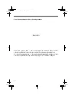
Page 16: ...uts and amp s HIGH INPUT CH1 CH2 and HIGH INPUT CH3 CH4 jacks Floating Ground Connection Common Ground Connection illustration show connections made with CH1 CH2 and CH3 CH4 wire harnesses between aut...

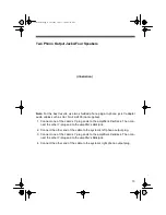
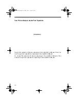
Page 17: ...uts and amp s HIGH INPUT CH1 CH2 and HIGH INPUT CH3 CH4 jacks illustration show connections made with CH1 CH2 and CH3 CH4 wire harnesses between autosound system s speaker outputs and amp s HIGH INPUT...

Page 18: ...r speakers properly phased connect to and to 1 With the speakers placed in their approximate locations run one speaker wire from each speaker to the amplifier 2 Separate each speaker wire s two conduc...

Page 19: ...of the speaker wire s unmarked conductor to the amplifier s BRIDGED CH1 terminal 4 Connect the other end of the wire to the left front speaker s negative termi nal 5 Repeat Steps 1 4 to connect speake...

Page 20: ...s you still use them for this unbridged connection This connection produces 125 watts per channel Use this connection if you do not have high power speakers You must select one terminal pair either BR...

Page 21: ...al 5 Repeat Steps 1 4 to connect speaker wires between the amplifier s BRIDGED CH2 or BRIDGED CH4 terminals and the right speaker s terminals 6 Set CH1 CH2 ST BRG and CH3 CH4 ST BRG to ST Two Speakers...

Page 22: ...nmarked conductor to the amplifier s BRIDGED CH2 terminal 4 Connect the other end of the wire to the left speaker s negative terminal 5 Connect one end of a speaker wire s marked conductor to the ampl...

Page 23: ...akers or to the BRIDGED CH3 and BRIDGED CH4 terminals rear speakers 2 If you used the front speaker connections in Step 1 connect the subwoofer to the amplifier s BRIDGED CH3 or BRIDGED CH4 and termin...

Page 24: ...to the amplifier s BRIDGED CH3 and BRIDGED CH4 terminals Or if you used the rear speaker connections in Step 1 connect the subwoofer to the amplifier s BRIDGED CH1 and BRIDGED CH2 terminals 3 Set X O...

Page 25: ...other end to the positive terminal of one of the subwoofers 2 Connect one end of the speaker wire s unmarked conductor to the amplifier s BRIDGED CH2 terminal then connect the wire s other end to the...

Page 26: ...your vehicle battery s negative terminal Then recheck your connections After you test the autosound system and amplifier and verify that everything is properly connected and working fol low the instr...

Page 27: ...behind the mounting surface 5 Attach the amplifier to the mount ing surface using the supplied sheet metal screws and washers 6 Reconnect the wiring 7 Reconnect the cable to the vehi cle battery s neg...

Page 28: ...HE AUDIO LEVEL For the best performance you must adjust CH1 CH2 LEVEL MIN MAX for both of the amplifier s channels to adjust the level of the audio signals that enter the amplifier CH1 CH2 LEVEL MIN M...

Page 29: ...o pro duce 6 Adjust the autosound system s volume control to a comfortable listening level ADJUSTING FREQUENCY CROSSOVER If you installed one or more subwoof ers and therefore set X OVER FREQ OFF ON t...

Page 30: ...c ing a Fuse on Page 33 Start the vehicle or set it to ACC Check all connec tions No sound Autosound system not turned on or vol ume set to minimum Amplifier s LEVEL MIN MAX controls set to minimum Am...

Page 31: ...LE CAUSE SUGGESTION No sound continued Power problems Check the amplifier s and autosound sys tem s fuses and replace them if nec essary see Replac ing a Fuse on Page 33 12 2010 fm Page 31 Tuesday Jul...

Page 32: ...o keep it looking new Do not use harsh chemicals cleaning solvents or strong deter gents to clean the amplifier Modifying or tampering with the amplifier s internal parts can cause a malfunction and m...

Page 33: ...store Replacing the AGU Type Fuse 1 Disconnect the cable from the vehicle battery s negative ter minal 2 Push together and twist the fuse holder s parts on the red power cable until they spring apart...

Page 34: ...d and pull it out 3 If the fuse is blown replace it Use only a blade type fuse with the proper rating The fuse must be 35 amps 4 Grasp the new fuse s plastic end and push it in 5 Reconnect the cable t...

Page 35: ...igh Input 100 Ohms Input Sensitivity for 10 THD Output Power Low Input 250 mV High Input 2 5V Maximum Current Draw 70 A Dimensions HWD 25 8 x 10¹³ 16 x 195 8 Inches 6 7 x 27 5 x 49 8 cm Net Weight 12...

Page 36: ...ing or other incidence of excess voltage or current b any repairs other than those provided by a RadioShack Authorized Service Facility c consumables such as fuses or batteries d cosmetic damage e tra...

Reviews: