background image

 
               The amplifier is overheated. 
               The speaker wires are shorted. 
               The ground wire is open. 
               The speaker's impedance is above or below the rated output 
               impedance. 
 
               The Amplifier's overload protection circuit automatically  
               shuts down when any one of the above conditions occurs.  If  
               this happens, turn off your sound system and let the 
               amplifier cool down before you restart. 
 
 
LISTENING SAFELY 
 
To protect your hearing, follow these guidelines: 
 
  Do not listen at extremely high volume levels.  Extended, high 
  volume listening can lead to permanent hearing loss. 
 
  Always start by setting the volume to the lowest level possible  
  before you begin listening then gradually increase the volume as 
  necessary. 
 
  Once you set the volume, do not increase it.  Over a period of time, 
  your ears adapt to the volume level, so a volume level that does not 
  cause discomfort might still damage your hearing. 


Summary of Contents for 120-1971

Page 1: ...vel speaker or low level pre amplifier input signals to match your stereo system s output for best performance Input Level Control Lets you adjust the level high or low of audio signals that enter the...

Page 2: ...Do not modify the amplifier s wiring as this voids its warranty For your permanent records we suggest you record the amplifier s serial number The number is on the bottom of the amplifier...

Page 3: ...nd test it to be sure it works Do not permanently mount the amplifier until you are sure the connections are correct CHOOSING A MOUNTING LOCATION Choose a mounting location that meets the following re...

Page 4: ...1 The Amp is overheated 2 The speaker wires are shorted 3 The speaker s impedance is below the rated output impedance 4 The output power terminals are shorted loaded down 5 The unit is broken...

Page 5: ...NOTE Many modern vehicle parts are made of plastic or other materials that do not conduct electricity You must connect the black ground wire to a metal part that is not insulated from the vehicle s fr...

Page 6: ...A cables for dash to trunk mounting We recommend Radio Shack Cat No 43 2356 Follow these steps to connect the stereo system s RCA jacks to the amplifier s LOW INPUT terminals 1 Plug the RCA cable into...

Page 7: ...ect the common speaker wires to both of the amplifier s L and R negative terminals 3 Connect the left speaker s positive wire to the amplifier s left terminal 4 Connect the left speaker s negative wir...

Page 8: ...ou turn on your radio cassette player The POWER indicator lights when the amplifier is on SETTING THE INPUT LEVEL CONTROL LEVEL lets you adjust the level of audio signals that enter the amplifier For...

Page 9: ...cool down before you restart LISTENING SAFELY To protect your hearing follow these guidelines Do not listen at extremely high volume levels Extended high volume listening can lead to permanent hearin...

Page 10: ...en lights fade at power up and the unit loses power A Check the 12 V power lead to make sure when you turn on the remote switch on the voltage level doesn t drop Make sure the power lead is heavy gaug...

Page 11: ...e of electronic devices and distort or melt plastic parts Handle the amplifier gently and carefully Dropping it can damage circuit boards and cases and can cause the amplifier to work improperly Keep...

Page 12: ...Response 20 20 000 Hz 3dB Input Impedance 10k Ohms Input Sensitivity for 10 THD Output Power Low Input 250mV High Input 2 5V Power Supply Voltage DC 14 4V Negative Ground 10 5 16V Matching Speaker Imp...

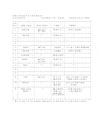
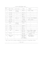
Page 13: ...GROUND 6 3mm r FORK TERMINAL 6 ORG WHT DIMMER STRIP SOLDER 7 PINK WHT PHONE MUTE 8 WHITE AWG 20 FRONT L 2p CORD 9 GRAY FRONT R 10 11 12 RED AWG 20 12 V TO 250 1A FUSE 24M M IGNITION TRANS STRIP SOLDER...

Page 14: ...RG WHT DIMMER STRIP SOLDER 7 PINK WHT PHONE MUTE 8 WHITE AWG 20 FRONT L 2p CORD 9 GRAY FRONT R 10 GREEN REAR L 11 VIOLET REAR R 12 RED AWG 20 12 V TO 250 1A FUSE 24M M IGNITION TRANS STRIP SOLDER 13 Y...

Page 15: ...SOLDER 7 PINK WHT PHONE MUTE 8 WHITE AWG 20 FRONT L 2p CORD 9 GRAY FRONT R 10 GREEN REAR L 11 VIOLET REAR R 12 RED AWG 20 12 V TO 250 1A FUSE 24M M IGNITION TRANS STRIP SOLDER 13 YELLOW 12 V TO 250 1A...

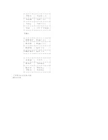
Page 16: ...White Right Brown Left Gray Left Red 12 V Power REAR GRN BLK Right WH BLK Right BR BLK Left GRAY BLK Left Orange S P L Black Ground Red w Memory White Backup CJD ir 02 28 96 LN 03 04...

Reviews: