background image


A-5230M2 / A-5260M2 Version 1.1


A-5230M2 / A-5260M2


Amplifier


SAFETY INSTRUCTIONS: 

 
IMPORTANT 

The wires in the mains lead are colored 
in accordance with the following code: 


GENERAL INSTALLATION 


¾


DO NOT

 run microphone cables near mains, data, telephone or 100 V line cables. 

¾


DO NOT

 run 100 V line cables near data, telephone or other low voltage cables. 

¾


DO NOT

 exceed 90 % of the amplifiers output power when using 100 V line (speech only). 

¾


DO NOT

 exceed 70 % of the amplifiers output power when using 100 V line (high level 

background music). 

¾


DO NOT

 use re-entrant horn loudspeakers for background music unless the loudspeaker has 

been specifically designed for this purpose. 

¾


AVOID

 jointing the Microphone cable, when this is unavoidable make sure a good screened 

connector is used, e.g. XLR. 

¾


ALWAYS

 use a balanced or floating low impedance microphone terminating into a balanced 

input on long microphone cable runs. 

¾


ALWAYS

 use a mains grade double insulated cable for the loudspeaker cable runs. 

¾


ENSURE

 that all loudspeakers are in-phase. 

¾


ENSURE

 that there are no short circuits on the loudspeaker line before connecting to the 

amplifier. 

Green & yellow 

Earth 

(E)

Blue 

Neutral 

(N)

Brown 

Live 

(L) 

As the colours of the wires in the mains lead of this 
apparatus do not correspond with the colored 
markings identifying the terminals in your plug 
proceed as follows:  
The wire, which is colored green and yellow, must 
be connected to the terminal, which is marked by 
the letter E, or by the safety earth symbol or colored 
green and yellow. The wire, which is colored blue, 
must be connected to the terminal, which is marked 
with the letter N or colored black. The wire, which is 
colored brown, must be connected to the terminal, 
which is marked with the letter L or colored red. 
If a 13 A (B.S.1363) plug or any other type of plug is 
used, a 5 A fuse must be fitted either in the plug or 
at the distribution board. 

Summary of Contents for A-5230M2

Page 1: ...AMPLIFICADOR CON FUENTES MUSICALES AMPLIFIER WITH MUSIC SOURCES A 5230M2 A 5260M2...

Page 2: ...ena calidad como los XLR UTILIZAR SIEMPRE micr fonos balanceados de baja impedancia o aislados de la masa conectados a entradas balanceadas si los cables son muy largos UTILIZAR SIEMPRE un cable doble...

Page 3: ...ONEXI N TELEF NICA TEL 5 6 6 CONEXI N DE SALIDA MOH MUSIC ON HOLD 5 6 7 CONEXI N A OTRAS FUENTES DE SE AL AUX 5 6 8 CONEXI N A LAS SALIDAS BOOSTER 6 6 9 CONEXI N A LOS ALTAVOCES 6 6 9 1 L nea de 100V...

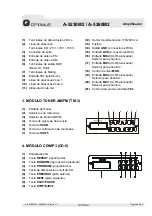
Page 4: ...en LINE 8 Control de graves BASS 9 Control de agudos TREBLE 10 Control de volumen MASTER 11 Interruptor de potencia ON OFF 12 Vumeter LED s para 20 6 0 dB 2 PANEL POSTERIOR 24V 0 COM 8 25V 70V 100V DC...

Page 5: ...a de SCAN 6 Tecla de confirmaci n de memorias 7 Tecla de SHIFT 4 M DULO CD MP3 CD 5 1 Pantalla del CD 2 Tecla REPEAT repetir pista 3 Tecla RANDOM reproducci n aleatoria 4 Tecla PROGRAM programaci n 5...

Page 6: ...1 3 2 1 3 2 1 3 2 1 AM FM M C U LCD KEY PAD Serv0 Drive M C U LCD KEY PAD VOX PHANTOM POWER Priority Priority CHIME TONE MASTER Priority VOX VU 100V 70V 25V 8ohm G ZONE1 ZONE2 POWER SWITCH 115V 230V...

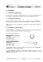
Page 7: ...d es la correcta Adem s intercalar un fusible de 15 A 6 3 CONEXI N DE LOS MICR FONOS La entrada de MIC1 es una entrada balanceada que utiliza un conector hembra jack est ndar de 6 3 mm de 3 polos en e...

Page 8: ...dem s 6 6 CONEXI N DE SALIDA MOH MUSIC ON HOLD El aparato dispone de 2 salidas MOH por las que saldr n las se ales de las entradas auxiliares Las salidas tienen un control de volumen independiente y n...

Page 9: ...ces de l nea de 100 V Todos los altavoces deben ser cableados en paralelo y la suma de las potencias de cada altavoz no debe exceder la potencia nominal del amplificador No es aconsejable cargar el am...

Page 10: ...aci n del reproductor de CD en modo STOP a Pulsar la tecla PROGRAM b Utilizar las teclas de avance y retroceso para seleccionar el pasaje deseado c Presione la tecla REPEAT para a adir el n mero del p...

Page 11: ...Hz 3 dB Distorsi n harm nica Inferior al 1 a 1 kHz Relaci n S N Todos los controles de volumen al m nimo 75 dB MIC1 a MIC4 60 dB AUX 70 dB TEL 70 dB Controles de tono Graves 10 dB a 100 Hz Agudos 10 d...

Page 12: ...n S N 80 dB Salida 850 mV Funciones EJECT STOP PAUSE PLAY tecla NEXT tecla PREVIOUS POWER PROGRAM RANDOM REPEAT 9 3 UNIDAD DE TUNER DIGITAL AM FM TM 3 Modelo TM 3 Rango de frecuencias FM 87 5 108 MHz...

Page 13: ...rminating into a balanced input on long microphone cable runs ALWAYS use a mains grade double insulated cable for the loudspeaker cable runs ENSURE that all loudspeakers are in phase ENSURE that there...

Page 14: ...NECTIONS 4 6 4 CHIME 5 6 5 TELEPHONE CONNECTION TEL 5 6 6 MOH Music On Hold OUTPUT CONNECTION 5 6 7 AUX Line CONNECTION 5 6 8 BOOSTER LINE OUTPUT CONNECTION 6 6 9 LOUDSPEAKER CONNECTION 6 6 9 1 100 V...

Page 15: ...rol 8 Master tone control BASS 9 Master tone control TREBLE 10 Master volume control all inputs except TEL 11 Power ON OFF switch 12 VU meter LEDs for 20 6 0 dB 2 REAR PANEL 24V 0 COM 8 25V 70V 100V D...

Page 16: ...4 Line output 2 RCA phono 3 FM AM TUNER UNIT TM 3 1 Tuner display 2 Memory keys 3 AM FM selection key 4 Frequency up down key 5 SCAN key 6 Set memory key 7 SHIFT key 4 CD MP3 PLAYER UNIT CD 5 1 CD dis...

Page 17: ...1 3 2 1 3 2 1 AM FM M C U LCD KEY PAD Serv0 Drive M C U LCD KEY PAD VOX PHANTOM POWER Priority Priority CHIME TONE MASTER Priority VOX VU 100V 70V 25V 8ohm G ZONE1 ZONE2 POWER SWITCH 115V 230V DC24V...

Page 18: ...must be fitted with an in line fuse quick blow type F15A When connecting batteries please ensure correct polarity 6 3 MICROPHONE CONNECTIONS MIC1 input is either a balanced standard 1 4 stereo jack on...

Page 19: ...l and they aren t affected by the master volume control They are used to output only auxiliary signals 600 1 V to feed an EPABX system Output level adjustable Please consult your EPABX handbook to use...

Page 20: ...se 100 V line loudspeakers with this output All loudspeakers are wired in parallel and the sum of the power tapping of each loudspeaker must not exceed the rated output of the amplifier ideally due to...

Page 21: ...f the disc TO cancel these functions press the REPEAT key 8 Programming the CD player in STOP mode a Press the PROGRAM key b Use the next or previous key to select a track c Press REPEAT key to memori...

Page 22: ...than 1 at 1kHz rated power Signal to noise ratio All Volume Controls C C W 75 dB below rated power MIC1 MIC4 60 dB below rated power AUX 70 dB below rated power TEL 70 dB below rated power Tone contr...

Page 23: ...dB Output 850 mV Function EJECT STOP PAUSE PLAY NEXT key PREVIOUS key POWER PROGRAM RANDOM REPEAT 9 3 AM FM DIGITAL TUNER TM 3 Model TM 3 Tuning range FM 87 5 108 MHz AM 522 1 620 kHz Sensitivity FM 2...

Reviews: