background image

AMPLIFICADOR

AMPLIFIER

AM-120

Manual de instalación y funcionamiento v1.0
Installation and operating instructions v1.0

Summary of Contents for Am-120

Page 1: ...AMPLIFICADOR AMPLIFIER AM 120 Manual de instalaci n y funcionamiento v1 0 Installation and operating instructions v1 0...

Page 2: ...ncia de salida de los amplificadores cuando se utiliza la l nea de 100 V para avisos NO SOBREPASAR el 70 de la potencia de salida de los amplificadores cuando se utiliza la l nea de 100 V para m sica...

Page 3: ...4 1 Conexi n a la red el ctrica 5 4 2 Entradas de audio 5 4 2 1 MIC 1 5 4 2 2 MIC 2 5 4 2 3 Entrada AUX CD 5 4 3 Terminales de prioridad manual 6 4 4 Conexi n de los altavoces 6 4 4 1 L nea de 100 V 6...

Page 4: ...limentaci n 1 Control de volumen MIC 1 2 Control de volumen MIC 2 3 Control de volumen AUX CD 1 Conector alimentaci n CA 2 Portafusibles 3 Tornillo de conexi n a masa 4 Terminales de prioridad manual...

Page 5: ...AM 120 Versi n 1 0 P gina 4 de 8 AM 120 Amplificador 3 DIAGRAMA DE BLOQUES...

Page 6: ...o no balanceada situado en la parte posterior del equipo El cableado se expone a continuaci n Cuerpo GND Punta Se al Gire el control frontal correspondiente en el sentido horario u antihorario para au...

Page 7: ...ficador trabaje en su nivel de salida nominal estos terminales de salida proporcionaran una tensi n de 100 V RMS Use nicamente altavoces para l nea de 100 V en esta salida Todos los altavoces se deben...

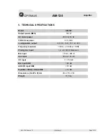
Page 8: ...z Salidas de altavoces 4 8 16 70 V y 100 V Respuesta en frecuencia 100 Hz 20 kHz 3 dB Entrada de micr fono prioridad 1 2 mV 600 Balanceado Entrada de micr fono 2 1 8 mV 600 Entrada auxiliar 300 mV 50...

Page 9: ...miento 5 La garant a carecer de validez cuando se observe Enmiendas o tachaduras en los datos del certificado de garant a o factura de compra Falta de factura original o falta de fecha en la misma Fal...

Page 10: ...run microphone cables near mains data telephone or 100V line cables DO NOT run 100V line cables near data telephone or other low voltage cables DO NOT exceed 90 of the amplifier s output power when us...

Page 11: ...NNECTIONS 5 4 1 AC mains connection 5 4 2 Audio inputs 5 4 2 1 MIC 1 5 4 2 2 MIC 2 5 4 2 3 AUX CD input 5 4 3 Manual priority contact 6 4 4 Loudspeakers connection 6 4 4 1 100 V line 6 4 4 2 70 V line...

Page 12: ...lume control 4 Equalization control 5 MASTER volume control 6 Power switch 7 Power indicator 1 AC Power plug 2 AC fuse holder 3 Ground connection screw 4 Manual priority contacts 5 Loudspeakers output...

Page 13: ...AM 120 Version 1 0 Page 4 of 8 AM 120 Amplifier 3 BLOCK DIAGRAM...

Page 14: ...1 4 Jack mono connector for unbalanced mic signal placed at amplifier rear panel Its pin out is as follow Slave GND Tip Signal Turn the correspondent front control knob clockwise or counter clockwise...

Page 15: ...nals Only use 100 V line loudspeakers with this output All loudspeakers are wired in parallel and the sum of their power must not exceed the rated output power of the amplifier It is advisable not to...

Page 16: ...0 Hz THD at max power 2 1kHz Loudspeakers output 4 8 16 70 V 100 V Frequency response 100 Hz 20 KHz 3 dB Priority mic input 1 2 mV 600 Balanced Mic input 1 8 mV 600 Aux input 300 mV 50 k CD input 1 1...

Page 17: ...lack of maintenance 5 The guarantee shall not be valid whenever the following is observed Amendments or corrections made to the details of the guarantee certificate or purchase invoice Failure to pro...

Reviews: