background image


AVR-A-OPT-02


                               Rev. 01 de 31/05/2016


OPTIMUS TECHNOLOGY

                                                                                                                    Página 3 de 35


I

NFORMAÇÕES 

S

OBRE 

S

EGURANÇA 

/


S

AFETY 

I

NFORMATION 

/


I

NFORMACIONES 

S

OBRE


S

EGURIDAD


Para  garantir  a  segurança  dos 
operadores,  a  correta  instalação 
do 

equipamento 

sua 

preservação, 

as 

seguintes 

precauções 

deverão 

ser 

tomadas: 
·  Só  está  autorizado  a  proceder 
instalação  deste  equipamento 
pessoas devidamente treinadas e 
autorizadas  pelo  fabricante  pois 
uma intervenção inadequada por 
alguém  não  capacitado  poderá 
causar danos  ao  equipamento  e 
ao gerador; 
 
· 

Deverão 

sempre 

ser 

observados  os  manuais  de 
instrução  e  a  etiqueta  de 
identificação do produto antes de 
proceder  a  sua  instalação, 
manuseio e parametrização; 
 
·  Deverão  ser  tomadas  as 
devidas 

precauções 

contra 

quedas,  choques  físicos  e/ou 
riscos 

à 

segurança 

dos 

operadores e do equipamento; 
 
· 

Sempre 

desconecte 

alimentação  geral  e  aguarde  a 
parada total da máquina antes de 
tocar  em  qualquer  componente 
elétrico 

associado 

ao 

equipamento,  isto  inclui  também 
os conectores de comandos. Não 
toque 

nos 

conectores 

de 

entradas  e  saídas  pois  altas 
tensões  podem  estar  presentes 
mesmo  após  a  desconexão  da 
alimentação 

mantenha-os 

sempre  isolados  do  restante  do 
circuito de comando principal do 
gerador. Verifique o item 9 deste 
manual 

para 

realizar 

desconexão do equipamento; 
 
· Observar as etiquetas de alerta 
coladas 

ao 

equipamento, 

“cuidado  tensão”  e  “cuidado 
superfície quente”; 
 
·  A  não  observação  dessas 
instruções 

poderá 

causar 

choques  ou  queimaduras  no 
operador  e  causar  danos  ao 
equipamento ou ao gerador; 
 
·  Este  Equipamento  atende  a 
norma IEC61010-1. 

To  guarantee  the  safety  of  the 
operators, the correct installation 
and proper operation of the 
equipment, 

the 

following 

precautions must be taken: 
 
·  They  are  only  allowed  to  carry 
out  installation  of  this  equipment 
people  properly  trained  and 
authorized  by  the  manufacturer 
as  an  inappropriate  intervention 
by  someone  not  trained  may 
cause damage to equipment and 
the generator; 
 
· The  product  instruction  manual 
and  product  identification  label 
must always be consulted before 
proceeding  with  its  installation, 
handling and parameter setting; 
 
· Adequate precautions should be 
taken  to  avoid  drops,  shocks 
and/or risks to the operators and 
the equipment; 
 
·  Always  disconnect  the  main 
power  supply  and  wait  for  the 
generator to come to a complete 
stop, 

before 

touching 

any 

electrical  component  associated 
with  the  equipment  including  the 
control connectors. Do not touch 
the  input  and  output  connectors 
since  high  voltages  may  be 
present even after the power has 
been switched off and keep them 
isolated  from  the  rest  of  the 
principal  command  circuit  of  the 
generator.    Check  item  9  of  this 
manual 

to 

disconnect 

the 

equipment; 
 
·  Observe  the  warning  labels 
attached  to  the  machine,  be 
careful  high  pressure  and  warm 
care; 
 
·  Failure  to  follow  these 
instructions may cause shocks or 
burns  to  the  operator  and 
damage  to  the  equipment  or 
generator; 
 
·  This  equipment  meets  the 
standard IEC 61010-1. 

Para  garantizar  la  seguridad  de 
los  operadores,  la  correcta 
instalación  del  equipo  y  su 
preservación, 

las 

siguientes 

precauciones 

deberán 

ser 

tomadas: 
· Sólo se le permite llevar a cabo 
la  instalación  de  este  equipo 
personas 

debidamente 

capacitadas y autorizadas por el 
fabricante pues una intervención 
inapropiada  por  alguien  no 
entrenado puede causar daños al 
equipo y al generador; 
 
· 

Deberán 

siempre 

ser 

observados  los  manuales  de 
instrucción  y  la  etiqueta  de 
identificación  del  producto  antes 
de  proceder  a  su  instalación, 
manoseo y parametrización; 
 
·  Deberán  ser  tomadas  las 
debidas  precauciones  contra 
caídas,  choques  físicos  y/o 
riesgos  a  la  seguridad  de  los 
operadores y del equipo; 
 
· 

Siempre 

desconecte 

la 

alimentación general y aguarde la 
parada total de la máquina antes 
de 

tocar 

en 

cualquier 

componente eléctrico asociado al 
equipo,  esto  incluye  también  los 
conectores  de  mando.  No  toque 
en  los  conectores  de  entradas  y 
salidas  pues  altos  voltajes 
pueden  estar  presentes  mismo 
después de la desconexión de la 
alimentación 

manténgalos 

siempre aislados del restante del 
circuito  de  mando  principal  del 
generador. Verifique en el ítem 9 
de este manual para desconectar 
el equipo; 
 
·  Tenga  en  cuenta  las  etiquetas 
de  advertencia  colocadas  en  el 
equipo,  “cuidado  voltaje”  y 
“cuidado superficie caliente”; 
 
·  El  incumplimiento  de  estas 
instrucciones 

puede 

causar 

choques  o  quemaduras  para  el 
operador y daños en el equipo o 
el generador; 
 
· El equipo hay de acuerdo con la 
norma IEC 61010-1. 

Summary of Contents for AVR-A-OPT-02

Page 1: ...de Instalação e Operação Installation and Operation Manual Manual de Instalación y Operación Revisão 01 de 31 de Maio de 2016 Revision 01 of May 31st 2016 Revisión 01 de 31 de Mayo de 2016 MOML00332 www optimustech ind br Rua Carlos Zerbin 105 Rio Hern Schroeder SC Brasil CEP 89 275 000 Fone 55 47 3307 7030 ...

Page 2: ...os derechos reservados Esta publicación no podrá bajo ninguna hipótesis ser reproducida almacenada o transmitida a través de ningún tipo de medios de comunicación ya sea electrónico impreso fonográfico o cualquier otro medio audiovisual sin previa autorización de OPTIMUS Technology Ltda Los infractores estarán sujetos a las penalidades previstas en ley Esta publicación está sujeta a alteraciones y...

Page 3: ... precautions should be taken to avoid drops shocks and or risks to the operators and the equipment Always disconnect the main power supply and wait for the generator to come to a complete stop before touching any electrical component associated with the equipment including the control connectors Do not touch the input and output connectors since high voltages may be present even after the power ha...

Page 4: ...ntacts and metallic parts damages to integrated circuits Properly packaged the regulator must be kept in a dry and well ventilated area away from direct sunlight rain wind and other adverse weather conditions in order to ensure the preservation of its operational functions After the regulator is properly packed and secured in such a way as to absorb shock and vibrations during shipment the same wi...

Page 5: ...reakers must be installed on or near the equipment an easily accessible place The installation should be done in a closed metal enclosure grounded or not so that the terminals become inaccessible with no opening that allows access to the equipment and its access should be made by means of a tool Philips screwdriver screwdriver etc remembering that neither the equipment terminals must be exposed no...

Page 6: ... Generator Connection With Auxiliary Coil Voltage 160 to 300Vca Conexión del Generador Con Bobina Auxiliar Voltaje 160 hasta 300Vca 20 5 4 Conexão do Gerador Com Bobina Auxiliar Tensão 320 a 600Vca Generator Connection With Auxiliary Coil Voltage 320 to 600Vac Conexión del Generador Con Bobina Auxiliar Voltaje 320 hasta 600Vca 22 6 Diagrama de Ligação Interna Internal Connection Diagram Diagrama d...

Page 7: ...nents for field flashing and its system is totally static and encapsulated in resin resistant to sea air fit to support the generator vibrations It features internal voltage adjustment via trimpot and external via potentiometer Its control system is adjusted by trimpot which adjusts the stability gain enabling a wide adjustment range which allows operation with the most diverse kinds of generators...

Page 8: ...juste interno de tensão VRal Internal voltage adjustment VRal Ajuste interno de voltaje VRal Ajustável via trimpot para toda a faixa de variação da tensão VRal Adjustable via trimpot for all voltage variation range VRal Ajustable vía trimpot para todo el rango de variación del voltaje VRal Ajuste externo de tensão via potenciômetro External voltage adjustment via potentiometer Ajuste externo de vo...

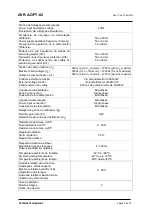
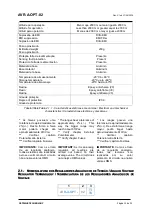
Page 9: ...terno de voltaje Via potenciômetro de 5KΩ 3W Via potentiometer of 5KΩ 3W A través de potenciómetro de 5KΩ 3W Ligação da realimentação Sensing connection Conexión de la realimentación Monofásica Single phase Monofásica Ligação da alimentação Power input connection Conexión de la alimentación Monofásica Single phase Monofásica Relação de ganho do retificador Kc Rectifier gain ratio Kc Relación de ga...

Page 10: ...racterísticas eléctricas y mecânicas As faixas possuem uma tolerância de aproximadamente 2 Desta forma a faixa maior poderá chegar até aproximadamente 610Vca Verificar capitulo Potenciômetro Externo Verificar capitulo Fusíveis IMPORTANTE Como se trata de um regulador analógico todas as leituras são realizadas pelo seu valor médio O circuito não analisa valores RMS The ranges bear a tolerance of ap...

Page 11: ...ystem failure short circuit The AVR A OPT 02 is fitted with a rectifier which controls the generator field voltage For the highest field voltage and field purely inductive the current supplied by input 3 is half the field current and the fuse maximum current must be a little more than half the current supplied by the regulator in the excitation system For field with addition and resistor in parall...

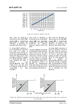
Page 12: ...to a excitação diminui reduzindo a tensão de saída do gerador A queda de tensão varia conforme o ajuste do Vad Na Figura 2 3 1 apresenta se a queda da tensão U F conforme a tensão Vad Para cada tensão Vad existe uma queda U F que fará com que a tensão de realimentação convirja a aproximadamente 0Vca zero Volts conforme a variação da frequência In Figure 2 3 1 the generator voltage variation graph ...

Page 13: ...mines the operation frequency between 50Hz and 60Hz The trimpot U F determines the actuation point of the mode U F which may be from the rated frequency Fn up to 1 3 of Fn whose value is factory adjusted in 10 below Fn For the operation in 60Hz it is adjusted in approximately 54Hz and for the operation in 50Hz it is adjusted for approximately 45Hz see Figure 2 3 2 whose value may be changed as per...

Page 14: ...enerator output voltage inside the adjusted value El funcionamiento se basa en la comparación del voltaje de detección RMS con el voltaje de referencia ajustado por la suma del potenciómetro Vad al potenciómetro externo El error es procesado por la red de realimentación cuyo valor determina el ángulo de disparo del tiristor que puede variar de 0 hasta 180 controlando así el voltaje de salida del g...

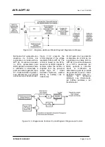
Page 15: ...ST1A presented by IEEE applied to systems where the rectifier is supplied from the generator output Type ST Static Excitation Systems whether directly by auxiliary coils or transformer En la Figura 2 4 2 se presenta el diagrama de control de los reguladores de voltaje AVR A OPT 02 El control está basado en el ST1A presentado por IEEE aplicado a sistemas donde el rectificador es alimentado a partir...

Page 16: ... metallic parts causing short circuits or electrical shocks The external potentiometer only decreases the voltage adjusted in Val When the potentiometer is used the voltage must be adjusted in the timpot Vad with the potentiometer adjusted in half resistance Ex 2 5KΩ for one potentiometer of 5KΩ Remove the jumper that releases the external potentiometer for its utilization of the same In the absen...

Page 17: ...entido horário aumenta a tensão Stb Ajuste da estabilidade Girar no sentido horário torna a resposta mais lenta U F Limitador U F Girar no sentido horário ajusta a frequência de atuação de U F Nota Poderá ser conectado potenciômetro para ajuste fino de tensão 5KΩ 3W nos bornes 6 e 7 com este símbolo Vad Voltage adjustment Turn clockwise to increase the voltage Stb Stability adjustment Turn clockwi...

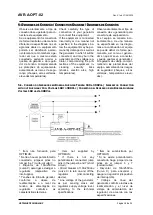
Page 18: ... el genera dor en que él se va a conectar y puede quemar el generador y el regulador de voltaje compro metiendo las protecciones del equipo aumentando los riesgos de seguridad choques arcos voltaicos temperaturas eleva das 5 1 CONEXÃO DO GERADOR SEM BOBINA AUXILIAR TENSÃO 160 A 300VCA GENERATOR CONNECTION WITHOUT AUXILIARY COIL VOLTAGE 160 TO 300VAC CONEXIÓN DEL GENERADOR SIN BOBINA AUXILIAR VOLTA...

Page 19: ...ción no puede exceder al voltaje má ximo especificado por el pro ducto 3 Si el voltaje de referencia no es igual al voltaje de salida del generador no efectúe las conexiones sin antes consultar la asistencia técnica 5 2 CONEXÃO DO GERADOR SEM BOBINA AUXILIAR TENSÃO 320 A 600VCA GENERATOR CONNECTION WITHOUT AUXILIARY COIL VOLTAGE 320 TO 600VAC CONEXIÓN DEL GENERADOR SIN BOBINA AUXILIAR VOLTAJE 320 ...

Page 20: ...clase de realimentación y el nivel de voltaje de alimentación del regulador de acuerdo con las especificaciones Atención 1 Antes de conectar el regula dor al generador verifique en el manual de instalación el voltaje nominal de referencia 2 El voltaje de alimentación no puede exceder al voltaje má ximo especificado por el pro ducto 3 Si el voltaje de referencia no es igual al voltaje de salida del...

Page 21: ...cting the regu lator to the generator 2 While using the auxiliary coil the connector E3 4 which is the reference circuit of the regula tor it is mandatory to be the common point between the coil and the generator 3 The supply voltage cannot exceed the maximum voltage specified by the product 4 If the reference voltage is not equal to the generator output voltage do not make connec tions without co...

Page 22: ... circuit 3 Circuit breaker of 10A 250Vac curve C to turn on and off the regulator disconnecting device Line voltage of the generator as per sensing class and regulator supply voltage level according to the technical specifications Attention 1 Check the rated reference voltage in the installation man ual before connecting the regu lator to the generator 2 While using the auxiliary coil the connecto...

Page 23: ...ém é recomendado inserir um diodo em série com o da fonte que está sendo utilizada para gerar a pré excitação evi tando a queima do regulador quando este passar a controlar a tensão de excitação Terminal 3 of power supply is di rectly connected to the terminal F and the terminal E3 4 inter connected through the thyristor to the terminal F If a pre excitation is necessary in the field it is recomme...

Page 24: ...05 2016 OPTIMUS TECHNOLOGY Página 24 de 35 7 DIMENSIONAL E SIMBOLOGIA DA SERIGRAFIA DIMENSIONAL AND SERIGRAPH SIMBOLOGY DIMENSIONAL Y SIMBOLOGÍA DE LA SERIGRAFÍA MM Versão TI TI version Versión TI Versão TS TS version Versión TS ...

Page 25: ...el equipo pueden llegar hasta 150 C 8 PRIMEIRA UTILIZAÇÃO FIRST UTILIZATION PRIMERA UTILIZACIÓN O regulador de tensão AVR A OPT 02 deve ser manipulado por técnico devidamente treinado Antes de iniciar a ligação certifique se de que o regulador é apropriado para utilização com o gerador verificando a etiqueta de característica Certifique se também das proteções existentes The voltage regulator AVR ...

Page 26: ...ligação incorreta O potenciômetro Stb correspondente ao ajuste de estabilidade deve ser colocado em meio curso Este potenciômetro influi somente na resposta dinâmica da máquina e não deve prejudicar o regime permanente O potenciômetro U F correspondente ao ajuste da proteção U F deve ser mantido na configuração de fábrica onde todos os equipamentos são testados e configurados antes da saída Se hou...

Page 27: ...não haja nenhuma tensão residual presente nos terminais do equipamento possibilitando assim o eventual acesso ao regulador de tensão A etiqueta abaixo é fornecida em formato impresso na forma de adesivo juntamente com o equipamento With U F protection configured correctly the generator shut off is done with the primary machine shut off To disconnect only the equipment without disconnecting the pri...

Page 28: ...aneira como descreve o procedimento o equipamento deverá ser enviado para avaliação pela assistência técnica OPTIMUS Below is the diagram for regulator connection on the bench where the equipment operation may be verified before connecting it to the generator Material required 1 Small screwdriver 1 Incandescent lamp 1 Lamp socket 1 Bipolar breaker 10A 250VAC curve C recommended 1 Extension cable 1...

Page 29: ...impot clockwise after a certain position of the trimpot the protection U F must act and the lamp shall remain on 6º Turn slightly the U F trimpot counter clockwise after a certain position of the trimpot the protection U F is disabled and the lamp will remain on 7º With the lamp on turn slightly the Vad trimpot counter clockwise after a certain position of the trimpot the lamp must turn off 8º Tur...

Page 30: ...ctado use batería externa 12Vcc para forzar la excitación 1 Invertir los cables F y F Tensão gerada oscila a vazio Voltage generated oscillates with no load Voltaje generado oscila sin carga Dinâmica desajustada Tensão de excitação do gerador muito pequena Dynamic misadjusted Generator excitation voltage too low Dinámica desajustada Tensión de excitación del generador muy pequeña Ajustar trimpot S...

Page 31: ...ificar el funcionamiento del regulador con el banco de pruebas descrito en el ítem 10 de este manual Para el regulador encapsulado efectuar su cambio 1 Para bateria de grupo gerador diesel onde o neutro do gerador estiver aterrado deverá sempre ser utilizada bateria independente 1 For battery of diesel generator group where the neutral of the generator is grounded an independent battery must alway...

Page 32: ...trained may cause damage to the equipment and the generator To execute the cleaning of the equipment disconnect it from the generator complying with the safety standards described on this manual ONLY REMOVE THE EQUIPMENT WITH THE MACHINE FULLY STOPPED The equipment can be cleaned with a dry cloth or a brush to remove all dust and debris accumulated If any damage occurs to the equipment disabling i...

Page 33: ...till present is the high temperature present in some circuit components and can be dampened if awaited a few minutes to cool the surface of the equipment soon after it can be accessed by adequately trained professionals Pay attention to execute the connections according to what is described in item 5 of the manual because as it was already mentioned if the equipment is connected incorrectly or in ...

Page 34: ...sks measured above providences should be taken for protection against such risks Check the previous chapter to learn how to reduce these risks Check the security condition of the equipment after repair as for example Check after the maintenance procedures that all connections have been made properly and are safe Check if the peripheral terminals are inaccessible Check if the voltage regulator has ...

Page 35: ... the software application if provided must first be reviewed and authorized in writing by OPTI MUS under penalty of loss of warranty A OP TIMUS disclaims any responsibility for mal function of the system changed by unauthor ized persons 3 The judgment of the requirements for the granting of warranty will be of responsibility of the engineering and commercial departments of OPTIMUS based on informa...

Reviews: