background image


AXD-30, AXD-60, AXD-120, AXD-240 

AXD-30/60/120/240 v1.3 

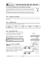
6.4.  AUX1 and AUX2 inputs 

These are asymmetric inputs through RCA connectors. 
They  have  a  sensitivity  that  can  be  adjusted  by  means  of  a  rear 

potentiometer (from -10dB to 0dB) 
For their connection, see Figure 12. 


6.5.  EMERGENCY input 

This  is  an  asymmetric  input  through  a  RJ45  connector,  with  a 
sensitivity of 0dB. 
Pin number 3 of the emergency connector supplies a voltage of 24V 

DC  (maximum  100mA)  which  can  be  used  to  supply  low 

consumption devices (MD-94, MD-94R  consoles...) 
It has a speech preference contact which is activated by joining pin 

no.  6  with  pin  no.  8  of  the  connector,  while  it  supplies  24V  DC 

(maximum 100mA) through the RELAY ACT strip. 
This input has priority over any other input of the amplifier. 
It  does  not  have  a  volume  control.  The  output  level  of  the 

emergency signal will always be at maximum volume. 
It  is  especially  suitable  for  receiving  emergency  announcements, 

which  take  priority  over  any  other  signal  (e.g.  evacuation 

messages). 
Cable STP of Cat 5 must be used for its connection (see Figure 13). 


6.6.  LINE OUT 

This  is  an  asymmetric  preview  output  through  a  male  XLR 

connector, with a sensitivity of 0dB. 
For its connection, see Figure 14. 


6.7.  PRE-OUT / POWER IN Connections 

PRE-OUT

:  Preview  output. 

This  is  an  asymmetric  output 

through  an  RCA  connector, 

with a sensitivity of 0dB. 

POWER-IN

: Input towards the 

power  phase.  This  is  an 

asymmetric  input  through  an 
RCA 

connector, 

with 

sensitivity of 0dB. 
They  are  used  to  install  a  unit 

(equaliser, 

antilarsen...) 

between  the  preview  and  the 

power  phase  of  the  amplifier 

(see Figure 15). 
If they are not used, they must 

have 

the 

interconnection 

jumper  positioned  between 

them. 
 

Figure 15 

Figure 13 

Figure 12 

Figure 14 

Summary of Contents for AXD-120

Page 1: ......

Page 2: ...y 5 conectores XLR 6 6 3 Configuraci n CHIME 6 6 4 Entradas AUX1 y AUX2 7 6 5 Entrada de EMERGENCIA 7 6 6 Salida LINE OUT 7 6 7 Conexiones PRE OUT POWER IN 7 6 8 Salida de l neas de altavoces 8 6 9 Mi...

Page 3: ...UX a bajas frecuencias Girando el potenci metro a la izquierda se aten an en 10 dB En la posici n central se obtiene una respuesta plana Girando el potenci metro a la derecha se acent an en 10 dB 9 Vo...

Page 4: ...de l neas de altavoces 27 Fusible de red 28 Red de 230 V c a 29 Rel auxiliar de seguridad de avisos 30 Conexi n de la masa al chasis 31 Entrada de alimentaci n por bater a 32 Toma de tierra 5 Vista po...

Page 5: ...conectores XLR con una sensibilidad de 60dB Para activar la preferencia de palabra es necesario unir el contacto de la regleta PRIORITY CONTROL INPUT a masa Ver figura 10 Opcionalmente se les puede a...

Page 6: ...ntrada del amplificador No dispone de control de volumen El nivel de salida de la se al de emergencia ser siempre a m ximo volumen Est especialmente indicada para recibir avisos de emergencia priorita...

Page 7: ...or est indicada en los terminales del mismo Esta potencia es en l nea de 100V Si se conecta el transformador a la l nea de 70V absorber la mitad de la potencia indicada y si se conecta a la l nea de 5...

Page 8: ...red Se encuentra situado en el cajet n inferior de la base de alimentaci n Tambi n hay un recambio en el mismo cajet n El valor del fusible var a en funci n del modelo de amplificador Modelo AXD 30 AX...

Page 9: ...itos de se al es aconsejable quitar el puente entre la masa y el chasis de todos los aparatos excepto uno evitando as ruidos provocados por los bucles del circuito de masas ver figura 22 6 15 Alimenta...

Page 10: ...ntal Funci n de prioridad Emergencia sobre micr fonos y auxiliares Micr fonos sobre auxiliares MIC1 sobre MIC2 Emergencia sobre micros y auxiliares Micros sobre auxiliares Micro 1 sobre micros 2 a 5 C...

Page 11: ...a la propiedad que pudieran causar el uso indebido del equipo incluyendo la falta de mantenimiento 5 La garant a carecer de validez cuando se observe Enmiendas o tachaduras en los datos del certifica...

Page 12: ......

Page 13: ...r 6 6 2 MIC 1 2 3 4 and 5 inputs XLR connectors 6 6 3 CHIME configuration 6 6 4 AUX1 and AUX2 inputs 7 6 5 EMERGENCY input 7 6 6 LINE OUT 7 6 7 PRE OUT POWER IN Connections 7 6 8 Loudspeakers line out...

Page 14: ...l level of the AUX inputs at low frequencies By turning the potentiometer to the left the bass is decreased by 10 dB In the central position a flat response is obtained By turning the potentiometer to...

Page 15: ...Expansion module 26 Loudspeakers line out 27 Mains fuse 28 Mains supply of 230V AC 29 Surety Paging relay 30 Earth to chassis connection 31 Battery power supply input 32 Earth connection 5 Rear panel...

Page 16: ...60dB To activate the speech preference join the contact of the PRIORITY CONTROL INPUT strip to the earth See Figure 10 Optionally a balanced line transformer can be connected to them in this case the...

Page 17: ...er It does not have a volume control The output level of the emergency signal will always be at maximum volume It is especially suitable for receiving emergency announcements which take priority over...

Page 18: ...ier The power absorbed by a loudspeaker with a transformer is indicated on its terminals This power is on the 100V line If the transformer is connected to the 70V line it will absorb half the indicate...

Page 19: ...Mains fuse This is located in the lower box of the power supply base There is also a spare fuse in the same box The value of the fuse varies depending on the amplifier model Model AXD 30 AXD 60 AXD 1...

Page 20: ...ctions are joined by the signal circuits it is advisable to remove the jumper between the earth connection and the chassis from all the units except one thereby avoiding noises caused by the loops of...

Page 21: ...ction Emergency over microphones and auxiliary inputs Microphones over auxiliary inputs MIC 1 over MIC 2 Emergency over microphones and auxiliary inputs Microphones over auxiliary inputs Micro 1 over...

Page 22: ...t including lack of maintenance 5 The guarantee shall not be valid whenever the following is observed Amendments or corrections made to the details of the guarantee certificate or purchase invoice Fai...

Page 23: ...SECURITY PAGING INFORMATION COMMUNICATION MUSIC www optimusaudio com Head Office C Barcelona 101 17003 Girona Spain Tel 34 972 203 300 e mail girona optimus es...

Reviews: