background image

ETAPAS DE POTENCIA

POWER AMPLIFIERS

MT-1500

MT-3500

Manual de instalación y funcionamiento
Installation and operating instructions

Summary of Contents for MT-1500

Page 1: ...ETAPAS DE POTENCIA POWER AMPLIFIERS MT 1500 MT 3500 Manual de instalaci n y funcionamiento Installation and operating instructions...

Page 2: ...imentaci n 6 4 MODOS DE FUNCIONAMIENTO 6 4 1 Funcionamiento est reo 6 4 2 Funcionamiento paralelo 6 5 INTERRUPTORES Y TECLAS DE CONTROL 6 5 1 Interruptor de alimentaci n AC y circuito de protecci n 6...

Page 3: ...erficies similares No use la unidad si el cable de alimentaci n est deteriorado o roto Conecte siempre la unidad mediante un cable de corriente alterna con toma de tierra No conecte la salida de otro...

Page 4: ...N y BANANAS 3 INSTALACI N Y FUNCIONAMIENTO 3 1 Desembalaje Abra cuidadosamente la caja de embalaje y compruebe que no haya ning n desperfecto Cada etapa de potencia es comprobada y verificada antes de...

Page 5: ...ctar el equipo a la red el ctrica aseg rese de que ste se encuentra ajustado a la tensi n de suministro adecuada El da o producido por conectar la unidad a una tensi n inadecuada no es cubierto por la...

Page 6: ...r el mal uso del equipo 3 7 Conexi n de entradas Las entradas est n disponibles en conectores XLR o jack est reo tienen una impedancia nominal de 20 k 10 k desbalanceadas y aceptan el nivel de se al d...

Page 7: ...dor ajuste los potenci metros de volumen al m nimo y ponga el selector de modo a la posici n STEREO 4 2 Funcionamiento paralelo En modo paralelo la se al de entrada se enviar hacia los dos canales de...

Page 8: ...te si el amplificador y la fuente de sonido no comparten la misma masa 6 INDICADORES LUMINOSOS El equipo dispone de cinco indicadores LED por canal PROTECT CLIP 6 30 y POWER Estos LEDs indican el esta...

Page 9: ...jar de 80 C 7 2 Cortocircuito En el caso de cortocircuito en la salida de l nea el circuito de protecci n ser m s sensible de lo habitual lo detectar inmediatamente y proteger los transistores finales...

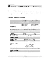
Page 10: ...1 kHz 4 0 15 a 20 Hz 20 kHz 8 0 2 a 20 Hz 20 kHz 4 0 015 a 1 kHz 8 0 03 a 1 kHz 4 0 15 a 20 Hz 20 kHz 8 0 2 a 20 Hz 20 kHz 4 Respuesta en Frecuencia 20 Hz 20 kHz 0 2 dB 8 1 W Factor Damping 200 por de...

Page 11: ...anced signals 5 3 8 Connecting outputs 5 3 9 Connecting power 6 4 OPERATING MODES 6 4 1 Stereo operation 6 4 2 Parallel operation 6 5 SWITCHES AND CONTROLS 6 5 1 AC power switch circuit breaker 6 5 2...

Page 12: ...ys operate the unit with the AC ground wire connected to the electrical system ground Do not run the output of any amplifier channel back into another channels input Do not parallel or series connect...

Page 13: ...n the shipping carton and check for any noticeable damage Every amplifier is completely tested and inspected before leaving the factory and should arrive in perfect condition If you find any damage no...

Page 14: ...onnecting the amplifier to improper AC voltage is not covered by the amplifier warranty Make sure the power switch is OFF before making system connections or plugging It is always a good idea to have...

Page 15: ...n female XLR connectors are also available Next figures provide examples of recommended connection techniques for each type of signal source 3 7 1 Jack inputs balanced signals Tip Hot signal Ring Cold...

Page 16: ...e one signal can be sent to both channels without external connection The audio signal is broadcasted from channel A input to channel A and channel B outputs The volume is controlled by means of chann...

Page 17: ...1 Protect LED When the red PROTECT LED lights red indicates that the channel has overheated the channel s output relay is open and the speaker has been disconnected This will happen if the amplifier s...

Page 18: ...ut transistors from over current stress The channel s PROTECT LED will light If the short circuit remains the channel will eventually thermally protect itself by disconnecting the load 7 3 DC voltage...

Page 19: ...kHz 4 Frequency Response 20 Hz 20 kHz 0 2 dB 8 1 W Damping Factor 200 under 8 S N 110 dB Slew Rate 38 V S 45 V S Voltage Gain AV 45 AV 68 Input Sensitivity Under 0 775 V RMS output Input Impedance 20...

Reviews: