background image


PM-CH7 Versión 1.0


Página 2 de 12


PM-CH7


Preamplificador


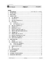
ÍNDICE 

1.


DESCRIPCIÓN ........................................................................................................ 3


2.


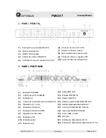
PANEL FRONTAL ................................................................................................... 4


3.


PANEL POSTERIOR ............................................................................................... 4


4.


CONEXIONES Y FUNCIONAMIENTO .................................................................... 5


4.1.


ENTRADA TEL / EMER (1) .......................................................................................... 5


4.2.


ENTRADA CH1 (3) ....................................................................................................... 5


4.3.


ENTRADAS CH2-CH6 (6 y 7) ...................................................................................... 5


4.4.


ENTRADAS CH7 .......................................................................................................... 5


4.4.1.


ENTRADA CD (9) ...............................................................................................................5


4.4.2.


ENTRADAS AUX / TUNER (10 y 11).................................................................................5


4.5.


SALIDA PRE OUT / ENTRADA POWER IN (12)......................................................... 5


4.6.


SALIDA TAPE OUT (14) .............................................................................................. 6


4.7.


SALIDA MASTER OUT (15 y 16) ................................................................................ 6


4.8.


CONECTOR DIN MASTER / SLAVE (17).................................................................... 6


4.9.


CONEXIÓN DE GND Y CHASIS (19) .......................................................................... 6


4.10.


OVERRIDE (20) ............................................................................................................ 6


4.11.


CONEXIÓN DE ALIMENTACIÓN 24 VCC (21) ........................................................... 6


4.12.


CONEXIÓN BATERIA 24 VCC (22) ............................................................................. 6


4.13.


INTERRUPTOR POWER ON / OFF (1)........................................................................ 6


4.14.


VUMETRO DE SALIDA (3) .......................................................................................... 6


5.


CONFIGURACIÓN .................................................................................................. 7


5.1.


PRIORIDAD .................................................................................................................. 7


5.2.


DIP SWITCH DE CONFIGURACIÓN CH1-CH6 (5) ..................................................... 7


5.2.1.


PARÁMETROS ESPECÍFICOS PARA EL CH1 ................................................................7


5.2.2.


PARÁMETROS PARA CANALES CH1-CH6 ....................................................................7


5.3.


FILTRO DE PALABRA ................................................................................................ 7


5.4.


VOX .............................................................................................................................. 8


5.5.


PUERTA DE RUIDO (VCA).......................................................................................... 8


6.


DIAGRAMA DE BLOQUES..................................................................................... 9


7.


SITUACION DE LOS JUMPERS EN EL PCB......................................................... 9


8.


ESPECIFICACIONES TÉCNICAS......................................................................... 10


9.


CERTIFICADO DE GARANTÍA ............................................................................. 12


Summary of Contents for PM-CH7

Page 1: ...PREAMPLIFICADOR PREAMPLIFIER PM CH7 Manual de instalaci n y funcionamiento v1 0 Installation and operating instructions v1 0...

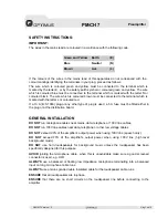
Page 2: ...erca telef nicos de datos o de baja tensi n NO SOBREPASAR el 90 de la potencia de salida de los amplificadores cuando se utiliza la l nea de 100 V para avisos NO SOBREPASAR el 70 de la potencia de sal...

Page 3: ...OUT 15 y 16 6 4 8 CONECTOR DIN MASTER SLAVE 17 6 4 9 CONEXI N DE GND Y CHASIS 19 6 4 10 OVERRIDE 20 6 4 11 CONEXI N DE ALIMENTACI N 24 VCC 21 6 4 12 CONEXI N BATERIA 24 VCC 22 6 4 13 INTERRUPTOR POWER...

Page 4: ...n nivel ajustable Filtro de palabra seleccionable para mejora de inteligibilidad de palabra Canal 7 para selecci n entre 3 entradas para fuentes musicales CD AUX o TUNER Entrada TEL EMER con prioridad...

Page 5: ...XLR del CH2 7 Entrada XLR del CH3 CH6 8 Dipswitch del CH3 CH6 9 Entrada de CD 10 Entrada auxiliar 11 Entrada Tuner 12 Salida PRE OUT 13 Entrada POWER IN 14 Salida TAPE OUT 15 Salida no balanceada MAS...

Page 6: ...viso configurable activado desde el contacto de prioridad 4 3 ENTRADAS CH2 CH6 6 y 7 Entradas balanceadas mediante conectores XLR con sensibilidad Micro L nea y alimentaci n phantom seleccionable 4 4...

Page 7: ...y importante que haya un solo punto de uni n entre la masa de se al y el contacto de tierra de la red Si la instalaci n de megafon a est compuesta por varios equipos probablemente tendr n los chasis u...

Page 8: ...PARA EL CH1 Chime Off en posici n Chime el equipo reproducir un gong de preaviso al activarse la prioridad del canal 1 Se puede regular el volumen del gong mediante el potenci metro situado en la par...

Page 9: ...ede ser habilitada o deshabilitada mediante jumpers JUMPER 1 JUMPER 2 JUMPER 3 JUMPER 4 JUMPER 5 JUMPER 6 de la placa PCB 5 5 PUERTA DE RUIDO VCA El equipo dispone de una puerta de ruido a nivel gener...

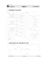
Page 10: ...PM CH7 Versi n 1 0 P gina 9 de 12 PM CH7 Preamplificador 6 DIAGRAMA DE BLOQUES 7 SITUACION DE LOS JUMPERS EN EL PCB...

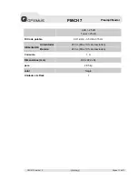
Page 11: ...lanceada Salidas Master Out 600 1V XLR balanceada RCA desbalanceada Tape Out 350 mV 4 7 k Pre Out 600 1 V Respuesta en Frecuencia CH1 CH6 Mic 60 15 000 Hz 3 dB CH1 CH6 Line 50 20 000Hz 3 dB CH7 CD Tun...

Page 12: ...lificador AUX 25 dB Tuner 25 dB Filtro de palabra CH1 CH6 3 5 dB a 315 Hz Alimentador 24 Vcc M x 10 de desviaci n Alimentaci n Bater a 24 Vcc M x 10 de desviaci n Consumo 1 A Dimensiones mm 438 x 222...

Page 13: ...enimiento 5 La garant a carecer de validez cuando se observe Enmiendas o tachaduras en los datos del certificado de garant a o factura de compra Falta de factura original o falta de fecha en la misma...

Page 14: ...n the plug or at the distribution board GENERAL INSTALLATION DO NOT run microphone cables near mains data telephone or 100V line cables DO NOT run 100V line cables near data telephone or other low vol...

Page 15: ...OUT 14 6 4 7 MASTER OUT 15 16 6 4 8 MASTER SLAVE DIN SOCKET 17 6 4 9 GROUND AND EARTH CONNECTION 19 6 4 10 OVERRIDE 20 6 4 11 POWER SUPPLY 24 V DC 21 6 4 12 BATTERY CONNEXION 24 V DC 22 6 4 13 POWER...

Page 16: ...le chime Selectable speech filters for improved intelligibility Channel 7 allows the selection of 3 music sources i e CD AUX or TUNER TEL EMER input terminal with VOX priority for telephone or emergen...

Page 17: ...CH1 CH2 dip switch control 6 CH2 XLR Input 7 CH3 CH6 XLR Input 8 CH3 CH6 Dipswitch 9 CD Input 10 Aux Input 11 Tuner Input 12 PRE OUT 13 POWER IN 14 TAPE OUT 15 Unbalanced MASTER OUT 16 Balanced MASTE...

Page 18: ...ority contact input Configurable preannouncement chime activated by priority contact 4 3 CH2 CH6 XLR INPUTS 6 7 Balanced XLR input connector with Mic Line input sensitivity and selectable phantom powe...

Page 19: ...lave unit equals to the music source of master unit The slave unit has its own priority state of each signal We suggest using slave unit music source connector for music source Then the master and sla...

Page 20: ...ast activated channel input has the highest priority and blocks all other channels including CH7 5 2 DIP SWITCH CH1 CH6 5 It is possible to change some equipment parameters by means of rear panel swit...

Page 21: ...ligibility by cutting off the lower frequencies 5 4 VOX The channels CH1 CH6 have VOX function that can be enabled or disabled by the corresponding jumper JUMPER 1 JUMPER 2 JUMPER 3 JUMPER 4 JUMPER 5...

Page 22: ...PM CH7 Version 1 0 P g 9 de 12 PM CH7 Preamplifier 6 BLOCK DIAGRAM 7 PCB JUMPERS...

Page 23: ...utputs Master out 600 1 V XLR Balanced RCA unbalanced Tape Out 350 mV 4 7 k Pre Out 600 1 V Frequency Response CH1 CH6 Mic 60 15 000 Hz 3 dB CH1 CH6 Line 50 20 000 Hz 3 dB CH7 CD Tuner AUX 50 Hz 20 00...

Page 24: ...ier AUX 25dB Tuner 25dB Speech Filter CH1 CH6 3 5 dB a 315 Hz Power supply Voltage DC 24V Max tolerance 10 Supply Battery Voltage DC 24V Max tolerance 10 DC power consumption 1 A Dimensions mm 438 x 2...

Page 25: ...ng lack of maintenance 5 The guarantee shall not be valid whenever the following is observed Amendments or corrections made to the details of the guarantee certificate or purchase invoice Failure to p...

Reviews: