background image


UMX-TEL version 4.3.000AS 

UMX-TEL 

(ASIA VERSION) 

DTMF Telephone interface card 

for UMX-03/0 audio matrix 

3.1.


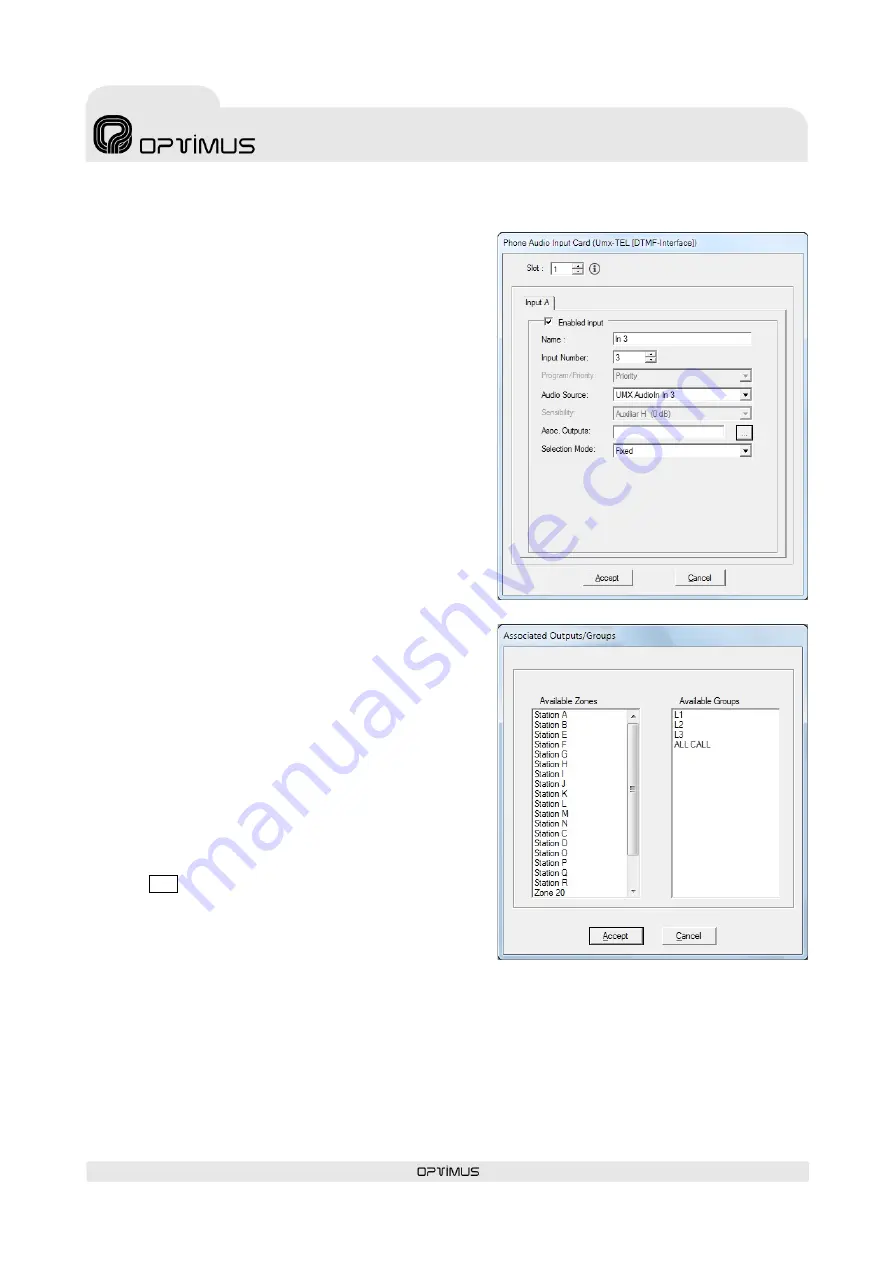
CONFIGURATION OF THE CARD 

The parameters of the card can be configured by using a PC connected 

to the UMX-03/0, using the 

P.A. Manager

 software.  

1.


Open the application from the server PC. 

2.


On the installations screen, edit or add a UMX-TEL card and 

configure the parameters of the input. 


Slot

. This is the position occupied by the card on the UMX-03/0 

(looking at a UMX-03/0 from the rear, slot 1 is the one on the 

right and slot 10 the one on the left). On a UMX-03/0 each card 

must be in a different slot. 


Enabled input

. This control enables or disables the input. 


Name

. Name of the input. Maximum of 20 characters. 


Input Number

. Also known as Logical Input. Using the numeric 

keyboard, enter a number between 1 and 9999. This number will 

be the one that identifies this input on the various menus of the 

UMX-03/0. There cannot be more than one input with the same 

number. 


Audio Source

. The audio source you select will have an assigned 

mode (priority with respect to the rest of the system's sound 

sources). This will be the mode assigned to the UMX-TEL card. 


Asoc. Outputs

. Configure this option if 

Fixed

  option has been 

selected in the 

Selection mode


Selection Mode

. Indicates the kind of destination to which the 

message will be sent: 
-


When 

Zones

 are selected, the card will send the message to 

the selected zone by DTMF dialling. 

-


When 

Groups

 are selected, the card will send the message 

to the selected group by DTMF dialling (the groups must be 

created beforehand by means of the P.A. Manager 

software). 

-


When 

Fixed

  is selected, the card will send the message to 

predefined zones or groups without necessity to select these 

zones by means of dialing.


These predefined zones are configured by the 

Asoc. Outputs


field

In order to introduce the associated outputs, click on the       

.

 ...  

 button and select the zones and groups from the list. 

For multiple selection, keep pressing the 

Ctrl.

  key while 

making the selection. 
To finalize, click on 

Accept

3.


Once the parameters have been configured, click on 

Accept

3.1.1.


SENDING CONFIGURATIONS 

To complete programming from the software, once the equipment unit has been configured, three operations are required: 
1.


Connect equipment:

 On the installation tree, right click with the mouse on the UMX-03/0 and select 

Connect

2.


Save the installation:

 Open the 

File

 menu and select 

Save

3.


Send configurations:

 On the installation tree, right click with the mouse on the UMX-03/0 whose configuration has changed 

and select 

Send configurations


Summary of Contents for UMX-TEL

Page 1: ...UMX TEL version 4 3 000AS 1 UMX TEL ASIA VERSION DTMF Telephone interface card for UMX 03 0 audio matrix 9I021T 21 06 2019 V4 3 000AS ...

Page 2: ......

Page 3: ... 2 2 FACTORY CONFIGURATION 9 3 2 3 CALL CONFIGURATION PROCESS 10 4 OPERATION 10 4 1 BROADCAST OF A MESSAGE WITHOUT A PASSWORD 10 4 2 BROADCAST OF A MESSAGE WITH A PASSWORD 10 4 3 CONFIGURATION EXAMPLE AND SENDING AN ANNOUNCEMENT 11 5 INSERTING THE CARD 12 6 TECHNICAL SPECIFICATIONS 13 7 SOFTWARE AND FIRMWARE VERSIONS 13 8 DOCUMENT VERSION TRACKING 13 9 GUARANTEE 14 WARNING This is a Class A unit I...

Page 4: ......

Page 5: ...nently lit This indicates that the card is broadcasting a message or the configuration parameters are being entered 4 CONFIG button This is used to configure the parameters of the card 3 CONFIGURATION OF THE SYSTEM Once it has been inserted in the chassis the UMX TEL card must be configured before it is used The UMX TEL card has two distinct types of configuration The first configuration which we ...

Page 6: ...gure this option if Fixed option has been selected in the Selection mode Selection Mode Indicates the kind of destination to which the message will be sent When Zones are selected the card will send the message to the selected zone by DTMF dialling When Groups are selected the card will send the message to the selected group by DTMF dialling the groups must be created beforehand by means of the P ...

Page 7: ...es before card answers 1 to 9 5 Debug mode 0 to 3 6 Number of digits for calling zones or groups or fix call 0 to 4 7 Detection time of DTMF 1 hanging up tone 0 to 9 8 Hanging up tone detection time 0 to 9 9 Noise gate 0 deactivated 1 activated 0 to 1 10 Maximum message time 0 to 9 PARAMETERS 1 2 and 3 PASSWORD These establish the three digits of the password P1 P2 P3 DESCRIPTION 0 0 0 Without pas...

Page 8: ...one by steps of 30 ms hanging up functionality by pressing 1 0 disabled 1 90 ms 9 330 ms P 7 DETECTION TIME OF DTMF 1 HANGING UP TONE 0 Hang up by pressing 1 deactivated 1 90 milliseconds 2 120 milliseconds 3 150 milliseconds 4 180 milliseconds 5 210 milliseconds 6 240 milliseconds 7 270 milliseconds 8 300 milliseconds 9 330 milliseconds PARAMETER 8 HANGING UP TONE DETECTION TIME According to the ...

Page 9: ...his determines the maximum communication time Once this time has elapsed the card will hang up automatically P10 MAXIMUM COMMUNICATION TIME 0 8 seconds 1 16 seconds 2 30 seconds 3 45 seconds 4 60 seconds 5 75 seconds 6 90 seconds 7 105 seconds 8 120 seconds 9 900 seconds 15 minutes 3 2 2 FACTORY CONFIGURATION The card will be factory configured as follows 0 0 0 2 0 0 2 4 0 2 Without password Answe...

Page 10: ...ter the established call tones from 1 to 9 depending on the configuration 4 The card answers and emits a series of short tones 5 If the card is configured with selection of zones or groups enter the digits of the zone or group where it is wished to broadcast the message If no number is entered in 9 seconds the card emits short tones and then hangs up If the zone entered is busy due to an announcem...

Page 11: ...E CARD 1 Press the CONFIG button on the rear panel of the card The CONFIG LED will start to blink quickly 2 Dial the telephone number corresponding to the card When the card answers the CONFIG LED will remain lit and THREE DIFFERENT TONES will be heard 3 Enter the ten digits parameters of the intended configuration in this case 1 2 3 2 0 2 2 2 0 2 4 THREE IDENTICAL TONES will be heard confirming t...

Page 12: ...e power supply to the unit POWER SUPPLY 1 and POWER SUPPLY 2 strips 2 Remove the rear blank plate for the slot where the card is to be inserted 3 Insert the card by fitting it into the slot guides and fasten it by means of the fastening screws 4 Reconnect the power Figure 5 ATTENTION If the UMX 03 0 audio matrix has any card configured with micro sensitivity 2 slots must be left between these card...

Page 13: ... version 4 3 7488 Linux version 2 6 35 14 PA Manager software Version 4 3 6309 8 DOCUMENT VERSION TRACKING Reference system Type of Document Confidentiality N A UMX 03 0 OPTIMAX 2 Installation and operation guide Rev Date Modifications Content Written by 1 0 15 09 2008 First version R D Department 1 1 12 11 2008 Factory configuration correction Hanging up by key 1 R D Department 1 2 22 03 2010 Upd...

Page 14: ...proper use of the equipment including lack of maintenance 5 The guarantee shall not be valid whenever the following is observed Amendments or corrections made to the details of the guarantee certificate or purchase invoice Failure to produce the original invoice or the absence of a date on this Absence of the serial or batch number on the equipment 6 In the case of personal computers the guarantee...

Page 15: ......

Page 16: ...9I021T V4 3 000AS 21 06 2019 ...

Reviews: