1. INTRODUCTION
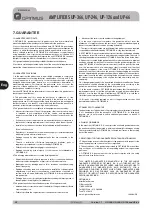
2. FRONTVIEW
Models UP-366, UP-246, UP-126 and UP-66 are amplifiers with an output of 360, 240, 120 and 60 Wats R.M.S.
respectyvely.
Suitable for use with public address systems, emergency announcements, background music and reproduction of
speech, they are remarkably strong and reliable.
Each model features an in-built circuit to protect against short circuit or overloading in the speaker line as well as a
termal protection circuit to prevent damage caused by overheating.
They occupy two standard 19” rack units.
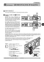
This indicates how much power is being fed to the line. The LED marked 0 dB shows the point at which the
amplifier provides maximum power.
Turning this clockwise will increase the volume of the program channel.These knobs are removable.
Turning this clockwise will increase the volume of the priority
channel.These knobs are removable.
This lights up when the priority channel is selected i.e. when pin no.
6 is linked to pin no. 8 at the priority input RJ45 connector.
This lights up when the protection circuit has been activated,
either as a result of an overload or short circuit in the speaker line
or overheating inside the unit.
This lights up when the
amplifier is connected to
the mains supply or is
being powered by a
battery source.
This turns the amplifier on
a n d
o f f
w h e n
i t
i s
connected to a mains
supply of 230V.a.c. This
switch does not have any
effect when the unit is
battery powered.
LEVEL INDICATOR
PROGRAM INPUT 'MASTER' REGULATOR
PRIORITY INPUT 'MASTER' REGULATOR
PRIORITY INDICATOR
PROTECTION INDICATOR
VENTILATION INPUT
T h i s
mu s t
b e
k e p t
unobstructed at all
times.
ON/OFF INDICATOR
ON/OFF SWITCH.
AMPLIFIERS UP-366, UP-246, UP-126 and UP-66
Eng
2
1
3
4
5
6
8
7
2
1
3
4
5
6
7
8
Once the volume has been adjusted the
system can be protected by removing the
buttons and replacing them with the
covers supplied in the bag of accessories.
Figure 1
E N G L I S H
1 4
UP-366, UP-246, UP-126 and UP-66
Version 1.1


