background image

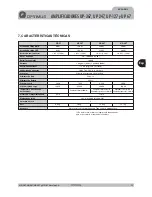
7. TECHNICAL SPECIFICATIONS

R.M.S. Output power

I.H.F. Output power

Total harmonic distortion

Bandwidt

Signal - noise ratio

Inputs

Input sensitivities

Speaker line output

Controls

Mains supply

Battery supply

Empty consumption

Full load consumption

Dimensions (mm)

Overheating protection

Fan activation temperature

Rack units

Weight

Finishes

120 W

60 W

UP-127

UP-67

240 W

UP-247

360 W

UP-367

< 0.5 % (1 kHz)

< 0.5 % (1 kHz)

< 0.5 % (1 kHz)

< 0.65 % (1 kHz)

50 ~ 18.000 Hz (±3 dB)

1 program (0 dBu), 1 priority (0 dBu)

775 mV (program and priority)

100 V, 70 V, 50 V / 4, 8, 16 ohms

Program and priority volume

230 V.c.a.

7,5 VA

16 VA

9.2 VA

16 VA

253 VA

138 VA

-

460 VA

736 VA

482.6 (w) x 88.8 (h) x 368.5 (d)

Iron front panel black painted. Iron cover black painted

> 80 dB

24 V.c.c.

110º C

95º C

Front fan:100º C*

Front fan: 65º C

Rear fan: 100º C*

Front fan: 65º C

Rear fan: 100º C*

2

10 kg

8.6 kg

13.6 kg

15.7 kg

(*) With respect to its size, the unit has been designed not to require the
ventilator except in extreme conditions.

482 W

162 W

82 W

312 W

Eng

2 1

UP-367, UP-247, UP-127 and UP-67

Version 1.0

E N G L I S H

AMPLIFIERS UP-367, UP-247, UP-127 and UP-67

Summary of Contents for UP-127

Page 1: ...UP 67 UP 127 UP 247 UP 367 N Manual de instrucciones AMPLIFICADOR Operating instructions AMPLIFIER Espa ol Espa ol English English UP 247...

Page 2: ......

Page 3: ...STERIOR 5 4 EL SISTEMA DE VENTILACI N 9 5 DIAGRAMA DE BLOQUES 10 6 CONFIGURACI N DE F BRICA 10 7 CARACTER STICAS T CNICAS 11 8 CERTIFICADO DE GARANT A 12 Esp ESPA OL AMPLIFICADORES UP 367 UP 247 UP 12...

Page 4: ...selecciona el canal de Priority es decir cuando se une el pin n 6 con el pin n 8 en el conector RJ45 de la Entrada de Prioridad Se ilumina cuando act a la Protecci n pudiendo ser debido a una sobreca...

Page 5: ...r de alimentaci n asegura el uso de diferentes tensiones de red Estos amplificadores salen de f brica preparados para funcionar a 230 V c a Bajo pedido se pueden suministrar preparados para otros volt...

Page 6: ...W Potencia absorbida por cada transformador de 10W 10W B Potencia total absorbida 60W Potencia absorbida por cada transformador de 10W 5W C Potencia total absorbida 60W Potencia absorbida por cada tra...

Page 7: ...TY INPUT PRIORITY OUTPUT PROGRAM INPUT PROGRAM OUTPUT ON OFF POWER AMPLIFIER 240W RMS 312W IHF UP 247 Engineered in EU Spain Made in China OPTIMUS S A PRI PRO RJ CONNECTION 6 PRIORITY 8 METAL SHIELD G...

Page 8: ...ten separar la pantalla del cable de la masa interna del aparato para cada uno de los conectores RJ 45 Normalmente est n en posici n ON pantalla y masa del aparato unidas Para separarlas debe situarse...

Page 9: ...parato superase los 110 C se activar a la protecci n del aparato Para sustituir los ventiladores en caso de aver a siga las figuras 10 y 11 4 EL SISTEMA DE VENTILACI N 14 Pin number 1 OSCILLATION INPU...

Page 10: ...J45 del conector PRIORITY OUTPUT ON Contacto de prioridad del RJ45 del conector PRIORITY INPUT ON Uni n de la se al de los canales PRIORITY y PROGRAM OFF Uni n de la pantalla del cable y el conector h...

Page 11: ...z 0 65 1 kHz 50 18 000 Hz 3 dB 1 programa 0 dBu 1 prioridad 0 dBu 775 mV programa y prioridad 100 V 70 V 50 V 4 8 16 ohms Volumen de programa y de prioridad 230 V c a 7 5 VA 16 VA 9 2 VA 16 VA 253 VA...

Page 12: ...imiento 5 La garant a carecer de validez cuando se observe Enmiendas o tachaduras en los datos del certificado de garant a o factura de compra Falta de factura original o falta de fecha en la misma Fa...

Page 13: ...FRONT VIEW 14 3 REAR VIEW 15 4 VENTILANTION SYSTEM 19 5 BLOCK DIAGRAM 20 6 FACTORY SETUP 20 7 TECHNICAL SPECIFICATIONS 21 8 GUARANTEE 22 13 UP 367 UP 247 UP 127 and UP 67 Version 1 0 Eng ENGLISH AMPLI...

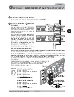
Page 14: ...up when the priority channel is selected i e when pin no 6 is linked to pin no 8 at the priority input RJ45 connector This lights up when the protection circuit has been activated either as a result...

Page 15: ...k mounted If the signals are also connected through the signal circuits it is advisable to remove the jumpers between the signal mass and the frame of all the units but one It is activated when the pr...

Page 16: ...50V 50V 50V 50V 70V 70V 70V 70V A A A A 100V 100V 100V 100V A Total input power 60W Power absorbed by each 10W transformer 10W B Total input power 60W Power absorbed by each 10W transformer 5W C Total...

Page 17: ...POWER AMPLIFIER 240W RMS 312W IHF UP 247 Engineered in EU Spain Made in China OPTIMUS S A PRI PRO RJ CONNECTION 6 PRIORITY 8 METAL SHIELD GND WHEN BALANCED 7 8 6 5 3 2 1 DIPSWITCH CONFIGURATION ON OF...

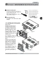
Page 18: ...cable shield from the internal mass of the unit for each of the RJ 45 connectors They are normally in the ON position shield and device mass connected To separate them place the corresponding dipswitc...

Page 19: ...itself would be activated To replace the rear and or front fan follow the indications in figures 10 and 11 4 VENTILATION SYSTEM 14 GND 1 8 1 8 JP2 internal jumper 15 Figure 10 Figure 9 Figure 11 Eng 1...

Page 20: ...utput connector ON Priority contact from the RJ45 Priority Input connector ON Priority and Program Audio link OFF Cable and RJ45 shield link to amplifier ground ON ON OFF PRI PRO LINK PRI PRO LINK SHI...

Page 21: ...3 dB 1 program 0 dBu 1 priority 0 dBu 775 mV program and priority 100 V 70 V 50 V 4 8 16 ohms Program and priority volume 230 V c a 7 5 VA 16 VA 9 2 VA 16 VA 253 VA 138 VA 460 VA 736 VA 482 6 w x 88...

Page 22: ...he following is observed Amendments or corrections made to the details of the guarantee certificate or purchase invoice Failure to produce the original invoice or the absence of a date on this Absence...

Page 23: ......

Page 24: ...3 300 Fax 34 972 218 413 E mail export optimus es E 48006 BILBO Zumalak rregui 48 Tel 944 598 116 122 775 Fax 944 730 596 E mail bilbo optimus es Tel 944 E 46015 VALENCIA Av Maestro Rodrigo 101 Tel 96...

Reviews: